ADRF5720
ADRF5720 is Silicon Digital Attenuator manufactured by Analog Devices.
Data Sheet
0.5 d B LSB, 6-Bit, Silicon Digital Attenuator, 9 k Hz to 40 GHz ADRF5720
Features
Ultrawideband frequency range: 9 k Hz to 40 GHz Attenuation range: 0.5 d B steps to 31.5 d B Low insertion loss with impedance match
2.0 d B up to 18 GHz 2.8 d B up to 26 GHz 4.5 d B up to 40 GHz Attenuation accuracy with impedance match ±(0.20 + 1.0% of attenuation state) up to 18 GHz ±(0.20 + 1.5% of attenuation state) up to 26 GHz ±(0.40+ 3.0% of attenuation state) up to 40 GHz Typical step error with impedance match ±0.25 d B up to 26 GHz ±0.65 d B up to 40 GHz High input linearity P0.1d B insertion loss state: 30 d Bm P0.1d B other attenuation states: 27 d Bm IP3: 50 d Bm typical High RF input power handling: 27 d Bm average, 30 d Bm peak Tight distribution in relative phase No low frequency spurious signals SPI and parallel mode control, CMOS/LVTTL patible RF amplitude settling time (0.1 d B of final RF output): 8 µs 24-terminal, 4 mm × 4 mm LGA package Pin-patible with ADRF5730, fast switching version
APPLICATIONS
Industrial scanners Test and instrumentation Cellular infrastructure: 5G millimeter wave Military radios, radars, electronic counter measures (ECMs) Microwave radios and very small aperture terminals (VSATs)
GENERAL DESCRIPTION
The ADRF5720 is a silicon, 6-bit digital attenuator with 31.5 d B attenuation control range in 0.5 d B steps.
This device operates from 9 k Hz to 40 GHz with better than 4.5 d B of insertion loss and excellent attenuation accuracy. The ATTIN port of the ADRF5720 has a radio frequency (RF) input power handling capability of 27 d Bm average and 30 d Bm peak for all states.
The ADRF5720 requires a dual supply voltage of +3.3 V and
- 3.3 V. The device Features serial peripheral interface (SPI), parallel mode control, and plementary metal-oxide semiconductor (CMOS)-/low voltage transistor to transistor logic (LVTTL)-patible controls.
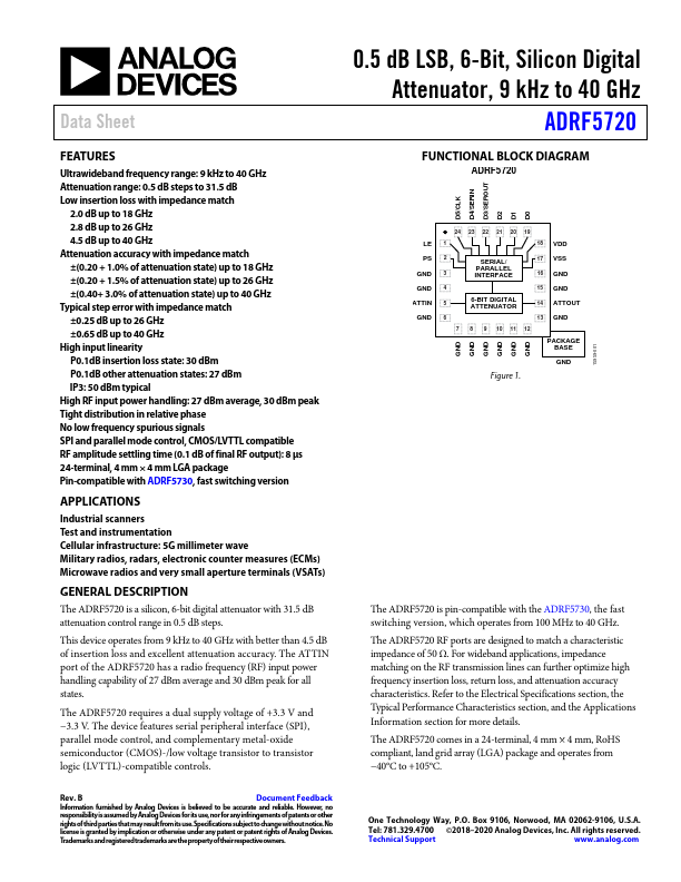
FUNCTIONAL BLOCK DIAGRAM
D5/CLK D4/SERIN D3/SEROUT D2 D1 D0
LE PS GND GND ATTIN GND
24 23 22 21 20...