Datasheet4U Logo Datasheet4U.com

ADSP-21992 - Mixed Signal DSP Controller

Description

3 DSP Core Architecture 3 Memory Architecture 5 Bus Request and Bus Grant 6 DMA Controller 7 DSP Peripherals Architecture 7 Serial Peripheral Interface (SPI) Port 7 DSP Serial Port (SPORT) 8 Controller Area Network (CAN) Module 9 Analog-to-Digital Conversion System 9 Voltage Reference 9 P

Features

  • ADSP-2199x, 16-bit, fixed-point DSP core with up to 160 MIPS sustained performance 48K words of on-chip RAM, as 32K words on-chip 24-bit program RAM, and 16K words on-chip, 16-bit data RAM External memory interface Dedicated memory DMA controller for data/instruction transfer between internal/external memory Programmable PLL and flexible clock generation circuitry enables full-speed operation from low speed input clocks IEEE JTAG Standard 1149.1 test access port supports on-chip emulation and sy.

📥 Download Datasheet

Full PDF Text Transcription (Reference)

The following content is an automatically extracted verbatim text from the original manufacturer datasheet and is provided for reference purposes only.

View original datasheet text
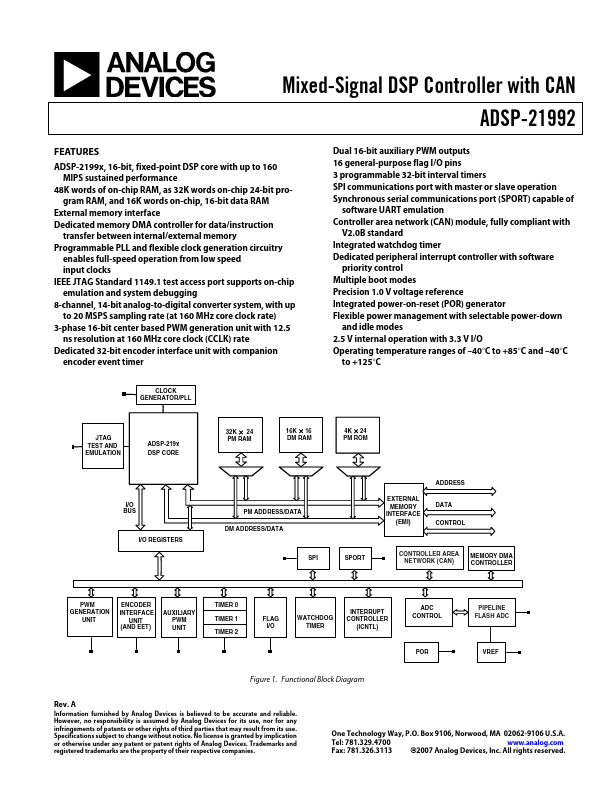
Mixed-Signal DSP Controller with CAN ADSP-21992 FEATURES ADSP-2199x, 16-bit, fixed-point DSP core with up to 160 MIPS sustained performance 48K words of on-chip RAM, as 32K words on-chip 24-bit program RAM, and 16K words on-chip, 16-bit data RAM External memory interface Dedicated memory DMA controller for data/instruction transfer between internal/external memory Programmable PLL and flexible clock generation circuitry enables full-speed operation from low speed input clocks IEEE JTAG Standard 1149.1 test access port supports on-chip emulation and system debugging 8-channel, 14-bit analog-to-digital converter system, with up to 20 MSPS sampling rate (at 160 MHz core clock rate) 3-phase 16-bit center based PWM generation unit with 12.
Published: |