LSW-0603
LSW-0603 is Wound Chip Inductor manufactured by Unknown Manufacturer.
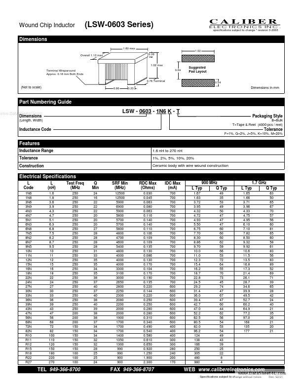
Features
Inductance Range Tolerance Construction 1.6 n H to 270 n H 1%, 2%, 5%, 10%, 20% Ceramic body with wire wound construction
Electrical Specifications
L Code
1N6 1N8 3N6 3N9 4N3 4N7 5N1 6N3 6N8 7N5 8N2 8N7 9N5 10N 11N 12N 15N 16N 18N 22N 24N 27N 30N 33N 36N 39N 43N 47N 56N 68N 72N 82N R10 R11 R12 R15 R18 R22 R27
L (n H)
1.6 1.8 3.6 3.9 4.3 4.7 5.1 6.3 6.8 7.5 8.2 8.7 9.5 10 11 12 15 16 18 22 24 27 30 33 36 39 43 47 56 68 72 82 100 110 120 150 180 220 270
Test Freq (MHz
250 250 250 250 250 250 250 250 250 250 250 250 250 250 250 250 250 250 250 250 250 250 250 250 250 250 250 200 200 200 150 150 150 150 150 150 100 100 100
Q Min
24 16 22 22 22 20 20 20 27 28 28 28 28 31 33 35 35 34 35 38 37 40 37 40 38 40 39 38 38 37 34 34 34 32 32 28 25 25 24
SRF Min (MHz)
12500 12500 5900 6900 5900 5800 5700 5700 5800 4800 4700 4600 5400 4800 4000 4000 4000 3300 3100 3000 2650 2800 2250 2300 2080 2200 2000 2000 1900 1700 1700 1700 1400 1350 1300 990 990 900 900
RDC Max (Ohms)
0.030 0.045 0.063 0.080 0.063 0.116 0.140 0.140 0.110 0.106 0.109 0.109 0.135 0.130 0.086 0.130 0.170 0.104 0.170 0.190 0.135 0.220 0.144 0.220 0.250 0.250 0.280 0.280 0.310 0.340 0.490 0.540 0.580 0.610 0.650 0.920 1.250 1.900 2.300
IDC Max (m A)
700 700 700 700 700 700 700 700 700 700 700 700 700 700 700 700 700 700 700 700 700 600 600 600 600 600 600 600 600 600 400 400 400 300 300 280 240 200 170
900 MHz L Typ Q Typ
1.67 1.63 3.72 3.95 4.32 4.72 4.93 5.50 6.75 7.70 8.30 8.86 9.70 10.0 11.0 12.3 15.4 16.2 18.7 22.8 24.5 29.2 31.4 36.0 39.4 42.7 47.0 52.2 62.5 80.5 82.0 96.2 124 138 166 250 305 480 980 49 35 53 49 50 47 47 47 60 60 60 62 59 66 53 72 64 55 70 73 45 74 47 67 47 60 44 62 56 54 53 54 49 43 39 25 22 8 4
L Typ
1.65 1.66 3.71 3.96 4.33 4.75 4.95 6.10 7.10 7.82 8.50 9.32 9.92 10.6 11.5 13.5 16.8 17.3 21.4 26.1 28.7 34.6 39.9 49.5 52.7 60.2 64.9 77.2 97.0 168 135 177
1.7 GHz Q Typ
63 50 65 67 70 57 56 60 81 65 60 58 61 83 56 83 89 52 69 71 39 65 28 42 24 40 21 35 26 21 20 21
TEL...