LSW-1008
LSW-1008 is Wound Chip Inductor manufactured by Unknown Manufacturer.
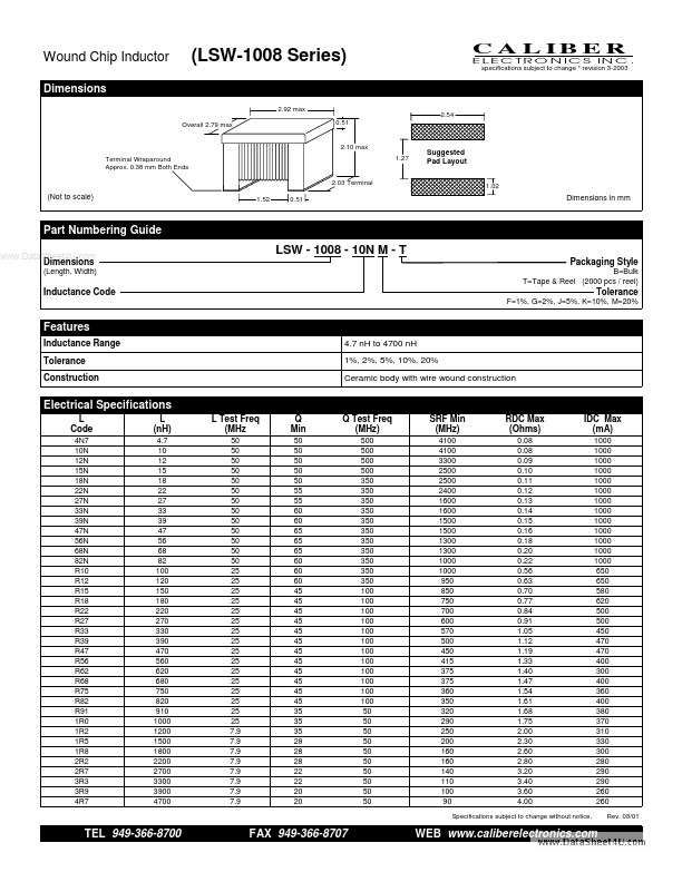
Features
Inductance Range Tolerance Construction 4.7 n H to 4700 n H 1%, 2%, 5%, 10%, 20% Ceramic body with wire wound construction
Electrical Specifications
L Code
4N7 10N 12N 15N 18N 22N 27N 33N 39N 47N 56N 68N 82N R10 R12 R15 R18 R22 R27 R33 R39 R47 R56 R62 R68 R75 R82 R91 1R0 1R2 1R5 1R8 2R2 2R7 3R3 3R9 4R7
L (n H)
4.7 10 12 15 18 22 27 33 39 47 56 68 82 100 120 150 180 220 270 330 390 470 560 620 680 750 820 910 1000 1200 1500 1800 2200 2700 3300 3900 4700
L Test Freq (MHz
50 50 50 50 50 50 50 50 50 50 50 50 50 25 25 25 25 25 25 25 25 25 25 25 25 25 25 25 25 7.9 7.9 7.9 7.9 7.9 7.9 7.9 7.9
Q Min
50 50 50 50 50 55 55 60 60 65 65 65 60 60 60 45 45 45 45 45 45 45 45 45 45 45 45 35 35 35 28 28 28 22 22 20 20
Q Test Freq (MHz)
500 500 500 500 350 350 350 350 350 350 350 350 350 350 350 100 100 100 100 100 100 100 100 100 100 100 100 50 50 50 50 50 50 50 50 50 50
SRF Min (MHz)
4100 4100 3300 2500 2500 2400 1600 1600 1500 1500 1300 1300 1000 1000 950 850 750 700 600 570 500 450 415 375 375 360 350 320 290 250 200 160 160 140 110 100 90
RDC Max (Ohms)
0.08 0.08 0.09 0.10 0.11 0.12 0.13 0.14 0.15 0.16 0.18 0.20 0.22 0.56 0.63 0.70 0.77 0.84 0.91 1.05 1.12 1.19 1.33 1.40 1.47 1.54 1.61 1.68 1.75 2.00 2.30 2.60 2.80 3.20 3.40 3.60 4.00
IDC Max (m A)
1000 1000 1000 1000 1000 1000 1000 1000 1000 1000 1000 1000 1000 650 650 580 620 500 500 450 470 470 400 300 400 360 400 380 370 310 330 300 280 290 290 260 260
Rev. 03/01
Specifications subject to change without notice.
TEL 949-366-8700
FAX 949-366-8707
WEB .caliberelectronics....