LSW-0805
LSW-0805 is Wound Chip Inductor manufactured by Unknown Manufacturer.
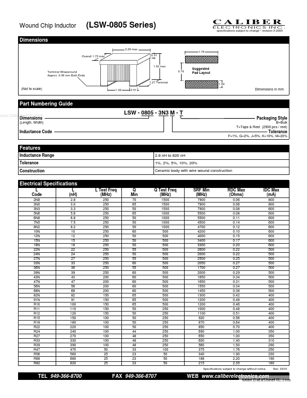
Features
Inductance Range Tolerance Construction 2.8 n H to 820 n H 1%, 2%, 5%, 10%, 20% Ceramic body with wire wound construction
Electrical Specifications
L Code
2N8 3N0 3N3 5N6 6N8 7N5 8N2 10N 12N 15N 18N 22N 24N 27N 33N 36N 39N 43N 47N 56N 68N 82N 91N R10 R11 R12 R15 R18 R22 R24 R27 R33 R39 R47 R56 R68 R82
L (n H)
2.8 3.0 3.3 5.6 6.8 7.5 8.2 10 12 15 18 22 24 27 33 36 39 43 47 56 68 82 91 100 110 120 150 180 220 240 270 330 390 470 560 680 820
L Test Freq (MHz)
250 250 250 250 250 250 250 250 250 250 250 250 250 250 250 250 250 200 200 200 200 150 150 150 150 150 100 100 100 100 100 100 100 50 25 25 25
Q Min
70 65 50 65 50 50 50 60 50 50 50 55 50 55 60 55 60 60 60 60 60 65 65 65 50 50 50 50 50 44 48 48 48 33 23 23 23
Q Test Freq (MHz)
1500 1500 1500 1000 1000 1000 1000 500 500 500 500 500 500 500 500 500 500 500 500 500 500 500 500 500 250 250 250 250 250 250 250 250 250 100 50 50 50
SRF Min (MHz)
7900 7900 7900 5500 5500 4500 4700 4200 4000 3400 3300 2600 2000 2500 2050 1700 2000 1650 1650 1550 1450 1300 1200 1200 1000 1100 920 870 850 690 650 600 560 375 340 188 215
RDC Max (Ohms)
0.06 0.06 0.08 0.08 0.11 0.14 0.12 0.10 0.15 0.17 0.20 0.22 0.22 0.25 0.27 0.27 0.29 0.34 0.31 0.34 0.38 0.42 0.48 0.46 0.48 0.51 0.56 0.64 0.70 1.00 1.00 1.40 1.50 1.76 1.90 2.20 2.35
IDC Max (m A)
800 800 600 600 600 600 600 600 600 600 600 500 500 500 500 500 500 500 500 500 500 400 400 400 400 400 400 400 400 350 350 310 290 250 230 190 180
Rev. 03/01
Specifications subject to change without notice.
TEL 949-366-8700
FAX 949-366-8707
WEB .caliberelectronics....