GENERAL DESCRIPTION
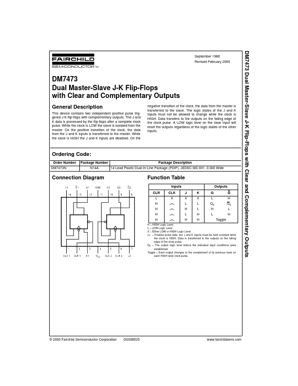
While the clock is LOW the slave is isolated from the master. On the positive transition of the clock, the data from the J and K inputs is transferred to the master. While the clock is HIGH the J and K inputs are disabled. On the negative transition of the clock, the data from the master is transferred to the slave. The logic states of the J and K inputs must not be allowed to change while the clock is HIGH. Data transfers to the outputs on the falling edge of the clock pulse. A LOW logic level on the clear input will reset the outputs regardless of the logic states of the other inputs. Ordering Code: Order Number DM7473N Package Number N14A Package DESCRIPTION
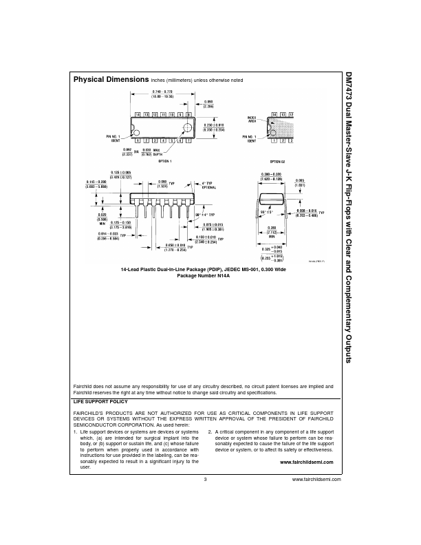
14-Lead Plastic Dual-In-Line Package (PDIP), JEDEC MS-001, 0.300 Wide Connection Diagram Function Table Inputs CLR L H H H H CLK J X L H L H K X L L H H Q L Q0 H L Toggle Outputs Q H Q0 L H H = HIGH Logic Level L = LOW Logic Level X = Either LOW or HIGH Logic Level = Positive pulse data. the J and K inputs must be held constant while the clock is HIGH. Fairchild Semiconductor