Fairchild Semiconductor IRF840B
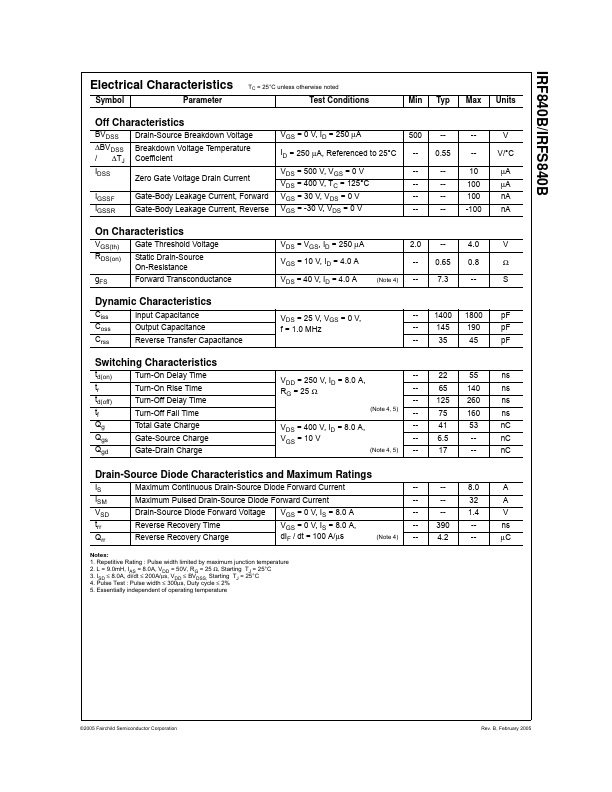
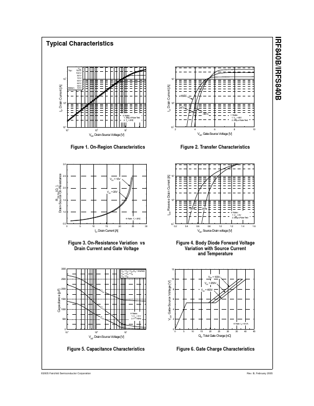
This advanced technology has been especially tailored to minimize on-state resistance, provide superior switching performance, and withstand high energy pulse in the avalanche and commutation mode. These devices are well suited for high efficiency switch mode power supplies, power factor correction and electronic lamp ballasts based on half bridge.| Part No. | IRF840B |
|---|---|
| Datasheet | IRF840B Download |
| Manufacturer |  Fairchild Semiconductor |
| Description | 500V N-Channel MOSFET |
| Buy | Stock & Price |
GENERAL DESCRIPTION
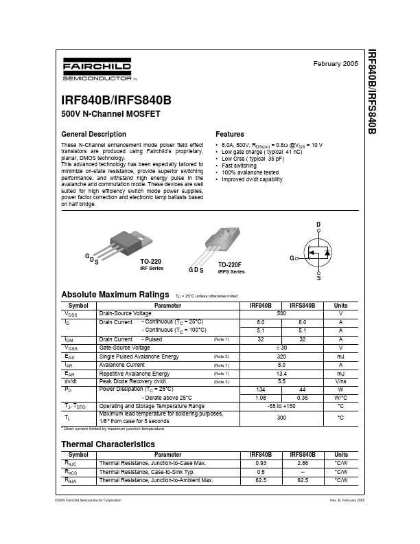
These N-Channel enhancement mode power field effect transistors are produced using Fairchild’s proprietary, planar, DMOS technology.FEATURES
● 8.0A, 500V, RDS(on) = 0.8Ω @VGS = 10 V● Low gate charge ( typical 41 nC)
● Low Crss ( typical 35 pF)
● Fast switching
● 100% avalanche tested
● Improved dv/dt capability D GD S TO-220 IRF Series GD S TO-220F IRFS Series G S
ABSOLUTE MAXIMUM RATINGS
TC = 25°C unless otherwise noted Symbol Parameter VDSS Drain-Source Voltage ID Drain Current - Continuous (TC = 25°C) - Continuous (TC = 100°C) IDM Drain Current - Pulsed (Note 1) VGSS Gate-Source Voltage EAS Single Pulsed Avalanche Energy (Note 2) IAR Avalanche Current (Note 1) EAR Repetitive Avalanche Energy (Note 1) dv/dt Peak Diode Recovery dv/dt (Note 3) PD Power Dissipation (TC = 25°C) - Derate above 25°C TJ, TSTG Operating and Storage Temperature Range TL Maximum lead temperature for soldering purposes, 1/8" from case for 5 seconds * Drain current limited by maximum junction temperature.