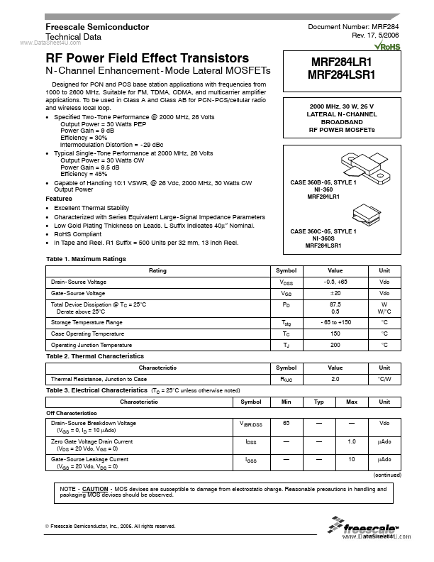
Datasheet4U Logo Datasheet4U.com

MRF284LR1 - RF Power Field Effect Transistors

General Description

Ferrite Beads, Round, Ferroxcube #56 - 590 - 65 - 3B 0.8 - 8.0 pF Gigatrim Variable Capacitors, Johanson #27291SL 22 mF, 35 V Tantalum Surface Mount Chip Capacitors, Kemet #T491X226K035AS4394 0.1 mF Chip Capacitors, Kemet #CDR33BX104AKWS 220 pF Chip Capacitor, ATC #100B221KP500X 1000 pF Chip Capacit

Key Features

  • Excellent Thermal Stability.
  • Characterized with Series Equivalent Large - Signal Impedance Parameters.
  • Low Gold Plating Thickness on Leads. L Suffix Indicates 40μ″ Nominal.
  • RoHS Compliant.
  • In Tape and Reel. R1 Suffix = 500 Units per 32 mm, 13 inch Reel. Table 1. Maximum Ratings Rating Drain - Source Voltage Gate - Source Voltage Total Device Dissipation @ TC = 25°C Derate above 25°C Storage Temperature Range Case Operating Temperature Operating Junc.

📥 Download Datasheet

Full PDF Text Transcription (Reference)

The following content is an automatically extracted verbatim text from the original manufacturer datasheet and is provided for reference purposes only.

View original datasheet text
www.DataSheet4U.com Freescale Semiconductor Technical Data Document Number: MRF284 Rev. 17, 5/2006 RF Power Field Effect Transistors N - Channel Enhancement - Mode Lateral MOSFETs Designed for PCN and PCS base station applications with frequencies from 1000 to 2600 MHz. Suitable for FM, TDMA, CDMA, and multicarrier amplifier applications. To be used in Class A and Class AB for PCN - PCS/cellular radio and wireless local loop. • Specified Two - Tone Performance @ 2000 MHz, 26 Volts Output Power = 30 Watts PEP Power Gain = 9 dB Efficiency = 30% Intermodulation Distortion = - 29 dBc • Typical Single - Tone Performance at 2000 MHz, 26 Volts Output Power = 30 Watts CW Power Gain = 9.