DESCRIPTION
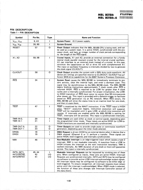
Table 1 - PIN DESCRIPTION
Symbol Vee, Vee Vss , Vss RESET Pin No. 9,43 26,60 57 Xl,X2 59,58 ClKOUT 56 RES 24 TEST 47 TMR IN 0, 20 TMR IN 1 21 TMR OUTO, 22 TMROUT 1 23 DROO, 18 DROl 19 NMI 46 INTO,INT1, INT2/1 NTAO, INT3/INTAl 45,44 42 41 Type I I 0 I o I I 0 0 I I I I I/O I/O Name and Function System Power: +5 V power supply. System Ground. Reset Output indicates that the MB l 80186 CPU is being reset, and can be used as a system reset. It is active HIGH, synchronized with the processor clock, and lasts an integer number of clock periods corresponding to the length of the RES signal. Crystal Inputs, Xl and X2, provide an external connection for a fundamental mode parallel resonant crystal for the internal crystal oscillator. Xl can interface to an external clock instead of a crystal. In this case, minimize the capacitance on X2 or drive X2 with complemented Xl. Clock Output provides the system with a 50% duty cycle waveform. All device pin timings are specified relative to ClOKOUT. Fujitsu