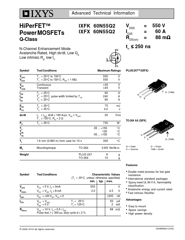
IXFK60N55Q2 Description
6 10 g g G = Gate S = Source.
IXFK60N55Q2 Key Features
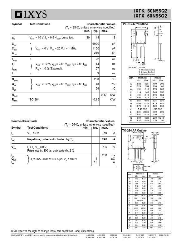
- ID25 Pulse test, t ≤ 300 µs, duty cycle d ≤ 2 %
- VDSS, ID = 0.5
- VDSS, ID = 0.5
- ID25 48 99 0.17 TO-264 0.15 S pF pF pF ns ns ns ns nC nC nC K/W K/W
- Gate 2
- Drain (Collector) 3
- Source (Emitter) 4
- Drain (Collector)
- ID25, pulse test