IXFK88N30P Description
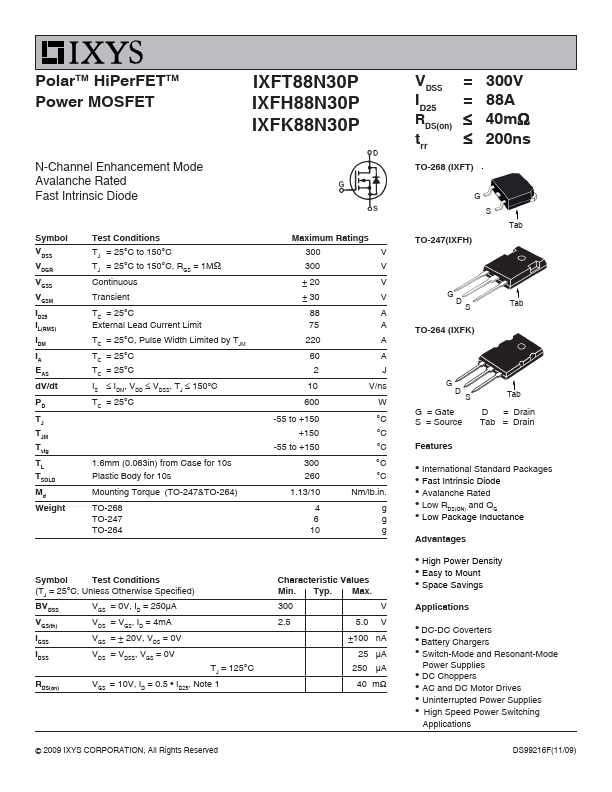
g g g TO-247(IXFH) G D S Tab TO-264 (IXFK) G D S Tab G = Gate S = Source.
IXFK88N30P Key Features
- ID25, Note 1
IXFK88N30P is Polar HiPerFET Power MOSFET manufactured by IXYS.
| Manufacturer | Part Number | Description |
|---|---|---|
| IXFK88N30P | PolarHT HiPerFET Power MOSFET |
g g g TO-247(IXFH) G D S Tab TO-264 (IXFK) G D S Tab G = Gate S = Source.