IXFR100N25
IXFR100N25 is HiPerFET Power MOSFETs manufactured by IXYS.
Advance Technical Information
Hi Per FETTM Power MOSFETs ISOPLUS247TM
(Electrically Isolated Backside) N-Channel Enhancement Mode Avalanche Rated, High dv/dt, Low trr
IXFR 100N25
VDSS ID25
RDS(on)
= 250 V = 87 A = 27 mΩ trr ≤ 250 ns
Symbol VDSS VDGR VGS VGSM ID25 IL(RMS) IDM IAR EAR EAS dv/dt PD TJ TJM Tstg TL VISOL Weight
Test Conditions TJ = 25°C to 150°C TJ = 25°C to 150°C; RGS = 1 MΩ Continuous Transient TC TC TC TC = 25°C (MOSFET chip capability) = External lead current limit = 25°C, Note 1 = 25°C
Maximum Ratings 250 250 ± 20 ± 30 87 75 400 100 64 3 5 400 -55 ... +150 150 -55 ... +150 V V V V A A A A m J J V/ns W °C °C °C °C V~ g
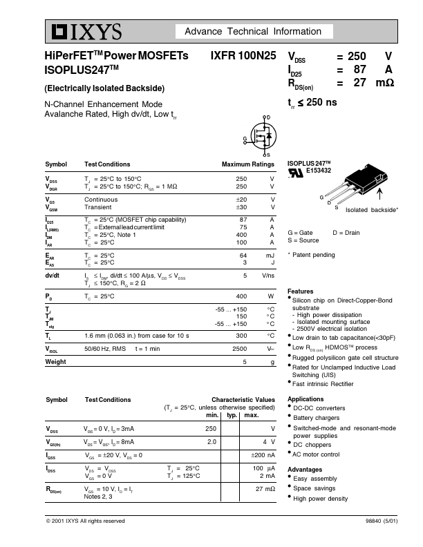
ISOPLUS 247TM E153432
Isolated backside-
G = Gate S = Source
D = Drain
TC = 25°C TC = 25°C IS ≤ IDM, di/dt ≤ 100 A/µs, VDD ≤ VDSS TJ ≤ 150°C, RG = 2 Ω TC = 25°C
- Patent pending
1.6 mm (0.063 in.) from case for 10 s 50/60 Hz, RMS t = 1 min
300 2500 5
Features l Silicon chip on Direct-Copper-Bond substrate
- High power dissipation
- Isolated mounting surface
- 2500V electrical isolation l Low drain to tab capacitance(<30p F) l l l
Low RDS (on) HDMOSTM process Rugged polysilicon gate cell structure
Rated for Unclamped Inductive Load Switching (UIS) l Fast intrinsic Rectifier Symbol Test Conditions Characteristic Values (TJ = 25°C, unless otherwise specified) min. typ. max. 250 2.0 V 4 V ±200 n A TJ = 25°C TJ = 125°C 100 µA 2 m A 27 mΩ Applications l DC-DC converters l l l l
Battery chargers Switched-mode and resonant-mode power supplies DC choppers AC motor control
VDSS VGS(th) IGSS IDSS RDS(on)
VGS = 0 V, ID = 3m A VDS = VGS, ID = 8m A VGS = ±20 V, VDS = 0 VDS = VDSS VGS = 0 V VGS = 10 V, ID = IT Notes 2, 3
Advantages l Easy assembly l l
Space savings High power density
© 2001 IXYS All rights...