Datasheet4U Logo Datasheet4U.com

IXGH20N100 - IGBT

Download the IXGH20N100 datasheet PDF. This datasheet also covers the IXGT20N100 variant, as both devices belong to the same igbt family and are provided as variant models within a single manufacturer datasheet.

Key Features

  • °C G = Gate, E = Emitter, C E C (TAB) C = Collector, TAB = Collector Maximum Lead temperature for soldering 1.6 mm (0.062 in. ) from case for 10 s Maximum Tab temperature for soldering SMD devices for 10 s Md Weight Mounting torque (M3) 1.13/10 Nm/lb. in. TO-247 AD TO-268 6 4 g g.
  • International standard packages JEDEC TO-268 surface and JEDEC TO-247 AD.
  • High current handling capability.
  • MOS Gate turn-on - drive simplicity.

📥 Download Datasheet

Note: The manufacturer provides a single datasheet file (IXGT20N100_IXYS.pdf) that lists specifications for multiple related part numbers.

Full PDF Text Transcription (Reference)

The following content is an automatically extracted verbatim text from the original manufacturer datasheet and is provided for reference purposes only.

View original datasheet text
IGBT 
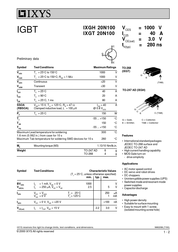
IXGH 20N100 IXGT 20N100 VCES IC25 VCE(sat) tfi(typ) = 1000 V = 40 A = 3.0 V = 280 ns Preliminary data Symbol VCES VCGR VGES VGEM IC25 IC90 ICM SSOA (RBSOA) PC TJ TJM Tstg www.DataSheet.co.kr Test Conditions TJ = 25°C to 150°C TJ = 25°C to 150°C; RGE = 1 MW Continuous Transient TC = 25°C TC = 90°C TC = 25°C, 1 ms VGE = 15 V, TVJ = 125°C, RG = 47 W Clamped inductive load, L = 100 mH TC = 25°C Maximum Ratings 1000 1000 ±20 ±30 40 20 80 ICM = 40 @ 0.8 VCES 150 -55 ... +150 150 -55 ... +150 300 260 V V V V A A A A TO-268 (IXGT) G E (TAB) TO-247 AD (IXGH) G W °C °C °C °C Features °C G = Gate, E = Emitter, C E C (TAB) C = Collector, TAB = Collector Maximum Lead temperature for soldering 1.6 mm (0.062 in.