Datasheet4U Logo Datasheet4U.com

IXGK35N120BD1 - IGBT

Download the IXGK35N120BD1 datasheet PDF. This datasheet also covers the IXGK35N120B variant, as both devices belong to the same igbt family and are provided as variant models within a single manufacturer datasheet.

Key Features

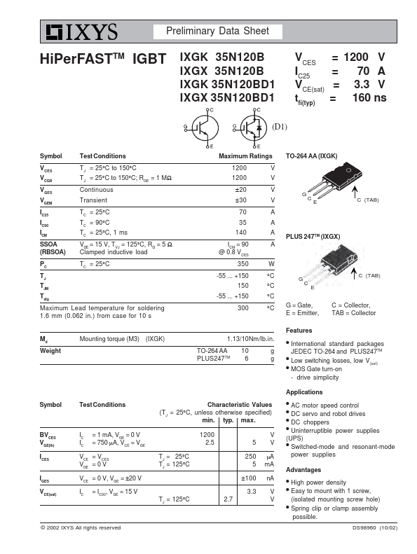
  • International standard packages JEDEC TO-264 and PLUS247TM.
  • Low switching losses, low V(sat).
  • MOS Gate turn-on - drive simplicity Symbol Test Conditions BVCES VGE(th) I CES IGES VCE(sat) IC = 1 mA, VGE = 0 V IC = 750 µA, VCE = VGE V =V CE CES VGE = 0 V VCE = 0 V, VGE = ±20 V IC = IC90, VGE = 15 V © 2002 IXYS All rights reserved Characteristic Values (TJ = 25°C, unless otherwise specified) min. typ. max. 1200 2.5 V 5V T= J 25°C TJ = 125°C 250 µA 5 mA ±100 nA TJ = 125°.

📥 Download Datasheet

Note: The manufacturer provides a single datasheet file (IXGK35N120B-IXYS.pdf) that lists specifications for multiple related part numbers.

Full PDF Text Transcription for IXGK35N120BD1 (Reference)

Note: Below is a high-fidelity text extraction (approx. 800 characters) for IXGK35N120BD1. For precise diagrams, and layout, please refer to the original PDF.

Preliminary Data Sheet HiPerFASTTM IGBT IXGK 35N120B IXGX 35N120B IXGK 35N120BD1 IXGX 35N120BD1 V = 1200 V CES IC25 = 70 A VCE(sat) = 3.3 V =tfi(typ) 160 ns (D1) Symbol T...

View more extracted text
1200 V CES IC25 = 70 A VCE(sat) = 3.3 V =tfi(typ) 160 ns (D1) Symbol Test Conditions V CES VCGR V GES VGEM IC25 I C90 ICM SSOA (RBSOA) T J = 25°C to 150°C TJ = 25°C to 150°C; RGE = 1 MΩ Continuous Transient TC = 25°C T C = 90°C TC = 25°C, 1 ms V GE = 15 V, T VJ = 125°C, R G = 5 Ω Clamped inductive load P C T C = 25°C TJ TJM Tstg Maximum Lead temperature for soldering 1.6 mm (0.062 in.) from case for 10 s Maximum Ratings 1200 1200 V V ±20 V ±30 V 70 A 35 A 140 A I = 90 CM @ 0.8 VCES 350 A W -55 ... +150 150 -55 ...