Datasheet4U Logo Datasheet4U.com

IXGP15N120B2 - IGBT

Download the IXGP15N120B2 datasheet PDF. This datasheet also covers the IXGA15N120B2 variant, as both devices belong to the same igbt family and are provided as variant models within a single manufacturer datasheet.

Key Features

  • International standard packages JEDEC TO-220AB and TO-263AA.
  • Low switching losses.
  • MOS Gate turn-on - drive simplicity Symbol Test Conditions (TJ = 25°C, unless otherwise specified) BV CES VGE(th) I C = 250 µA, V GE = 0 V IC = 250 µA, VCE = VGE ICES VCE = VCES V =0V GE I GES V CE = 0 V, V GE = ±20 V VCE(sat) IC = ICE90, VGE = 15 Characteristic Values Min. Typ. Max. 1200 2.5 V 5.0 V TJ = 25°C T J = 125°C 100 µA 3.5 mA ±100 nA TJ = 125.

📥 Download Datasheet

Note: The manufacturer provides a single datasheet file (IXGA15N120B2-IXYS.pdf) that lists specifications for multiple related part numbers.

Full PDF Text Transcription (Reference)

The following content is an automatically extracted verbatim text from the original manufacturer datasheet and is provided for reference purposes only.

View original datasheet text
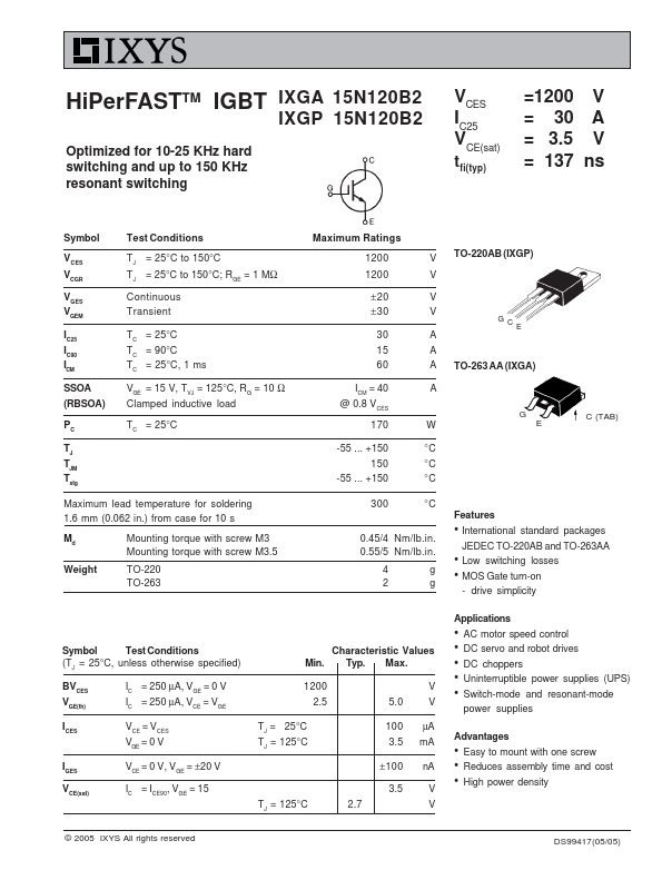
HiPerFASTTM IGBT IXGA 15N120B2 IXGP 15N120B2 Optimized for 10-25 KHz hard switching and up to 150 KHz resonant switching VCES IC25 VCE(sat) tfi(typ) =1200 V = 30 A = 3.5 V = 137 ns Symbol Test Conditions VCES VCGR VGES VGEM IC25 IC90 I CM SSOA (RBSOA) TJ = 25°C to 150°C TJ = 25°C to 150°C; RGE = 1 MΩ Continuous Transient TC = 25°C TC = 90°C T C = 25°C, 1 ms V GE = 15 V, T VJ = 125°C, R G = 10 Ω Clamped inductive load PC TC = 25°C TJ TJM Tstg Maximum lead temperature for soldering 1.6 mm (0.062 in.) from case for 10 s Md Weight Mounting torque with screw M3 Mounting torque with screw M3.5 TO-220 TO-263 Maximum Ratings 1200 1200 ±20 ±30 30 15 60 I = 40 CM @ 0.8 V CES 170 -55 ... +150 150 -55 ...