Overview: 
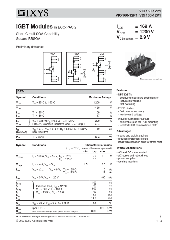
VID 160-12P1 VIO160-12P1 VDI 160-12P1 IGBT Modules in ECO-PAC 2
Short Circuit SOA Capability Square RBSOA IC25 = 169 A VCES = 1200 V VCE(sat) typ. = 2.9 V Preliminary data sheet VIO VID VDI AC1 SV18 IK10 X15 L9
NTC
A X15 X16 L9 T16
S NTC
X16 F1 B3
Pin arangement see outlines LMN IJK IK10 PS18 AC1 IGBTs
Symbol
VCES
VGES
IC25 IC80
ICM VCEK
tSC (SCSOA)
Ptot Conditions Maximum Ratings TVJ = 25°C to 150°C 1200 ± 20 V V TC = 25°C TC = 80°C
VGE = ±15 V; RG = 6.8 Ω; TVJ = 125°C RBSOA, Clamped inductive load; L = 100 µH
VCE = VCES; VGE = ±15 V; RG = 6.8 Ω; TVJ = 125°C non-repetitive 169 117
200 VCES
10 A A A
µs TC = 25°C 694 W Symbol Conditions Characteristic Values
(TVJ = 25°C, unless otherwise specified) min. typ. max. VCE(sat) IC = 160 A; VGE = 15 V; TVJ = 25°C TVJ = 125°C 2.9 3.3 V GE(th) I = 4 mA; V = V
C GE CE 4.5 ICES VCE = VCES; VGE = 0 V; TVJ = 25°C TVJ = 125°C IGES VCE = 0 V; VGE = ± 20 V td(on) t
r
td(off) t
f
Eon Eoff Inductive load, TVJ = 125°C V = 600 V; I = 100 A
CE C
VGE = 15/0 V; RG = 6.8 Ω 100 60
600 90
16.1 14.6 C V = 25 V; V = 0 V; f = 1 MHz ies CE GE 6.5 RthJC RthJH (per IGBT) with heatsink compound (0.42 K/m.K; 50 µm) 0.36 IXYS reserves the right to change limits, test conditions and dimensions. 3.5 V
6.5 V
6 mA 19 mA
400 nA
ns ns ns ns mJ mJ
nF
0.