IRF7351PbF
IRF7351PbF is Power MOSFET manufactured by International Rectifier.
Applications l Synchronous Rectifier MOSFET for Isolated DC-DC Converters l Low Power Motor Drive Systems
- 97436
HEXFET® Power MOSFET
VDSS
RDS(on) max
Qg (typ.)
60V 17.8mΩ@VGS = 10V 24nC
Benefits l Ultra-Low Gate Impedance l Fully Characterized Avalanche Voltage and Current l 20V VGS Max. Gate Rating
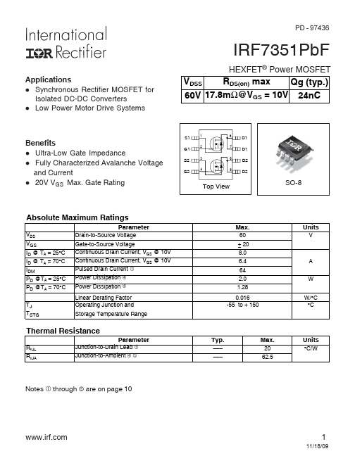
S1 1 G1 2 S2 3 G2 4
8 D1 7 D1 6 D2 5 D2
Top...