IRFR9110PBF
IRFR9110PBF is HEXFET Power MOSFET manufactured by International Rectifier.
- 95324A
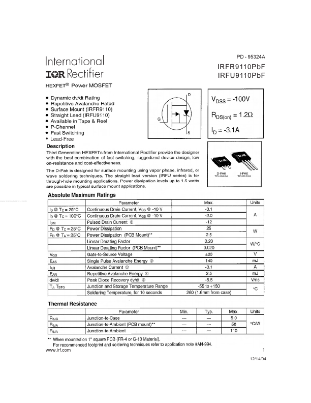
IRFR9110Pb F IRFU9110Pb F
- Lead-Free
..
.irf.
12/14/04
IRFR/U9110Pb F
.irf.
IRFR/U9110Pb F
.irf.
IRFR/U9110Pb F
.irf.
IRFR/U9110Pb F
.irf.
IRFR/U9110Pb F
.irf.
IRFR/U9110Pb F
Peak Diode Recovery dv/dt Test Circuit
+
Circuit Layout Considerations
- Low Stray Inductance
- Ground Plane
- Low Leakage Inductance Current Transformer
+ +
- - dv/dt controlled by RG
- ISD controlled by Duty Factor "D"
- D.U.T.
- Device Under Test
+
- -
Reverse Polarity for P-Channel
- - Use P-Channel Driver for P-Channel Measurements
Driver Gate Drive P.W. Period...