IRS2308PbF
IRS2308PbF is HALF-BRIDGE DRIVER manufactured by International Rectifier.
Features
- Floating channel designed for bootstrap operation
- Fully operational to +600 V
- Tolerant to negative transient voltage, d V/dt
- Gate drive supply range from 10 V to 20 V
- Undervoltage lockout for both channels
- 3.3 V, 5 V, and 15 V input logic patible
- Cross-conduction prevention logic
- Matched propagation delay for both channels
- Outputs in phase with inputs
- Logic and power ground +/- 5 V offset.
- Internal 540 ns deadtime
- Lower di/dt gate driver for better noise immunity
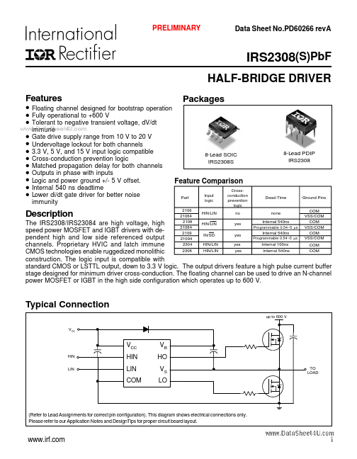
Packages
.. immune
8-Lead SOIC IRS2308S
8-Lead PDIP IRS2308
Feature parison
Part 2106 21064 2108 21084 2109 21094 2304 2308 Input logic HIN/LIN Crossconduction prevention logic no Dead-Time Ground Pins VSS/ VSS/ VSS/
Description none Internal 540ns
The IRS2308/IRS23084 are high voltage, high HIN/LIN yes Programmable 0.54~5 µs speed power MOSFET and IGBT drivers with de Internal 540ns IN/SD yes pendent high and low side referenced output Programmable 0.54~5 µs yes Internal 100ns HIN/LIN channels. Proprietary HVIC and latch immune Internal 540ns HIN/LIN yes CMOS technologies enable ruggedized monolithic construction. The logic input is patible with standard CMOS or LSTTL output, down to 3.3 V logic. The output drivers feature a high pulse current buffer stage designed for minimum driver cross-conduction. The floating channel can be used to drive an N-channel power MOSFET or IGBT in the high side configuration which operates up to 600 V.
Typical Connection up to 600 V
VB HO VS LO
TO LOAD
HIN LIN
(Refer to Lead Assignments for correct pin configuration). This diagram shows electrical connections only. Please refer to our Application Notes and Design Tips for proper circuit board layout.
.irf.
PRELIMINARY
IRS2308(S)Pb F
Absolute Maximum Ratings
Absolute maximum ratings indicate sustained limits beyond which damage to the device may occur. All voltage parameters are absolute voltages referenced to . The thermal resistance and power...