IRFBA31N50L Description
Units Conditions D MOSFET symbol 31 showing the A G integral reverse 124 S p-n junction diode. 1.5 V TJ = 25°C, IS = 31A, VGS = 0V 180 ns TJ = 125°C, IF = 31A 800 nC di/dt = 100A/µs Intrinsic turn-on time is negligible (turn-on is dominated by LS+LD) Typical SMPS Topologies l Zero Voltage Switching Full and Half Bridge Circuits .irf. 1 6/2/00 IRFBA31N50L Symbol V(BR)DSS ∆V(BR)DSS/∆TJ PROVISIONAL Static @ TJ =...
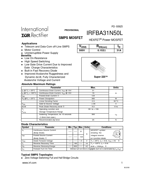
IRFBA31N50L Key Features
- Motor Control
- UninterruptIble Power Supply Benefits
- Low On-Resistance
- High Speed Switching
- Low Gate Drive Current Due to Improved Gate Charge Characteristics
- Built in Fast Recovery Diode
- Improved Avalanche Ruggedness and Dynamic dv/dt, Fully Characterized Avalanche Voltage and Current
- VDSS 500V RDS(on) 0.152Ω ID 31A Super-220™