C08051Cxxxx
C08051Cxxxx is CERAMIC CHIP CAPACITORS manufactured by Kemet Corporation.
..
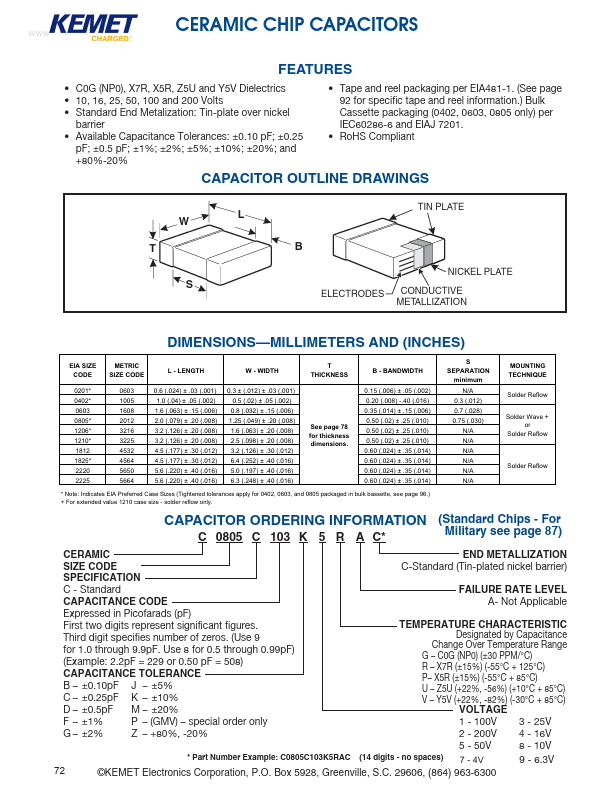
CERAMIC CHIP CAPACITORS
Features
- C0G (NP0), X7R, X5R, Z5U and Y5V Dielectrics
- 10, 16, 25, 50, 100 and 200 Volts
- Standard End Metalization: Tin-plate over nickel barrier
- Available Capacitance Tolerances: ±0.10 pF; ±0.25 pF; ±0.5 pF; ±1%; ±2%; ±5%; ±10%; ±20%; and +80%-20%
- Tape and reel packaging per EIA481-1. (See page 92 for specific tape and reel information.) Bulk Cassette packaging (0402, 0603, 0805 only) per IEC60286-6 and EIAJ 7201.
- RoHS pliant
CAPACITOR OUTLINE DRAWINGS
ELECTRODES
TIN PLATE
NICKEL PLATE CONDUCTIVE METALLIZATION
DIMENSIONS- MILLIMETERS AND (INCHES)
EIA EIA SIZE SIZE CODE
CODE
0402-
SIZE CODE
METRIC SIZE CODE...