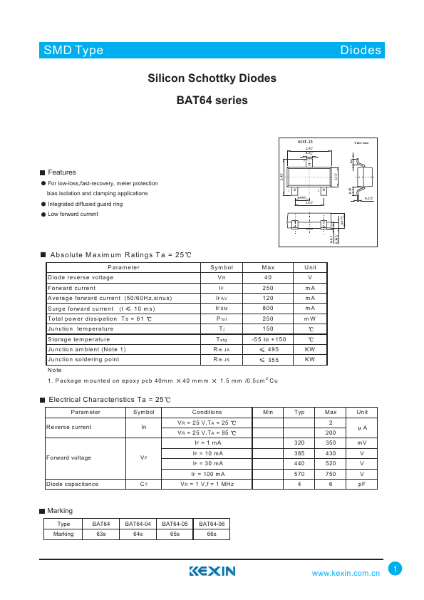
FEATURES
For low-loss,fast-recovery, meter protection bias isolation and clamping applications Integrated diffused guard ring Low forward current +0.12.4 -0.1 SOT-23 2.9+0.1 -0.1 0.4+0.1 -0.1 3 12 0.95+0.1 -0.1 1.9+0.1 -0.1 Absolute M axim um R atings Ta = 25 Param eter Diode reverse voltage Forward current Average forward current (50/60Hz,sinus) Surge forward current (t 10 m s) Total power dissipation Ts = 61 Junction tem perature Storage tem perature Junction am bient (Note 1) Junction soldering point N o te 1. Package m ounted on epoxy pcb 40m m Sym bol VR IF IFAV IFSM P tot Tj T stg R th JA R th JS Max 40 250 120 800 250 150 -55 to +150 495 355 40 m m m 1.5 m m /0.5cm 2 Cu U n it V mA mA mA mW KW KW ELECTRICAL CHARACTERISTICS
Ta = 25 P aram eter Symbol Reverse current IR Forward voltage Diode capacitance VF CT Conditions VR = 25 V,TA = 25 VR = 25 V,TA = 85 IF = 1 mA IF = 10 mA IF = 30 mA IF = 100 mA VR = 1 V,f = 1 MHz Min Typ Max 2 200 320 350 385 430 440 520 570 750 46 0-0.1 +0.10...