DESCRIPTION
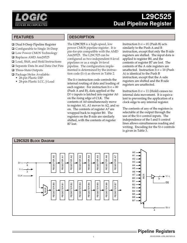
The configuration implemented is determined by the instruction code (I1-0) as shown in Table 2. The I1-0 instruction code controls the internal routing of data and loading of each register. For instruction I1-0 = 00 (Push A and B), data applied at the D 7-0 inputs is latched into register A0 on the rising edge of CLK. The contents of A0 simultaneously move to register A1, A1 moves to A2, and so on. The contents of register A7 are wrapped back to register B0. The registers on the B side are similarly shifted, with the contents of register B7 lost. Instruction I1-0 = 01 (Push B) acts similarly to the Push A and B instruction, except that only the B side registers are shifted. The input data is applied to register B0, and the contents of register B7 are lost. The contents of the A side registers are unaffected. Instruction I1-0 = 10 (Push A) is identical to the Push B instruction, except that the A side registers are shifted and the B side registers are unaffected. Instruction I1-0 = 11 (Hold) causes no internal data movement. LOGIC Devices Incorporated