LS7217
LS7217 is PHOTO CONTROLLED OUTDOOR LIGHTING manufactured by LSI.
FEATURES
:
- Input interface to a LDR or a photo transistor
- Programmable Duration Selection
- Shunt regulator
- 50Hz / 60Hz time base selection
- Relay Driver output
- 6.0V ± 0.75V operating voltage range (VDD
- VSS)
- LS7217 (DIP), LS7217-S (SOIC)
- See Figure 1
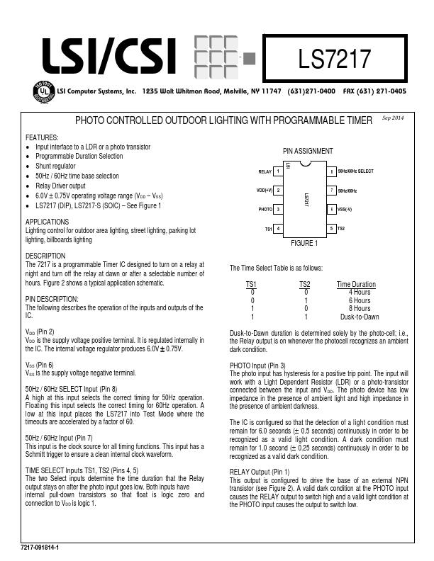
PIN ASSIGNMENT
APPLICATIONS Lighting control for outdoor area lighting, street lighting, parking lot lighting, billboards lighting
DESCRIPTION
The 7217 is a programmable Timer IC designed to turn on a relay at night and turn off the relay at dawn or after a selectable number of hours. Figure 2 shows a typical application schematic.
PIN DESCRIPTION
: The following describes the operation of the inputs and outputs of the IC.
FIGURE 1
The Time Select Table is as follows:
TS1 TS2 00 01 10 11
Time Duration 4 Hours 6 Hours 8 Hours
Dusk-to-Dawn
VDD (Pin 2) VDD is the supply voltage positive terminal. It is regulated internally in the IC. The internal voltage regulator produces 6.0V ± 0.75V.
Dusk-to-Dawn duration is determined solely by the photo-cell; i.e., the Relay output is on whenever the photocell recognizes an ambient dark condition.
VSS (Pin 6) VSS is the supply voltage negative terminal.
50Hz / 60Hz SELECT Input (Pin 8) A high at this input selects the correct timing for 50Hz operation. Floating this input selects the correct timing for 60Hz operation. A low at this input places the LS7217 into Test Mode where the timeouts are accelerated by a factor of 60.
50Hz / 60Hz Input (Pin 7) This input is the clock source for all timing functions. This input has a Schmitt trigger to ensure a clean internal clock waveform.
TIME SELECT Inputs TS1, TS2 (Pins 4, 5) The two Select inputs determine the time duration that the Relay output stays on after the photo input goes low. Both inputs have internal pull-down transistors so that float is logic zero and connection to VDD is logic 1.
PHOTO Input (Pin 3) The photo input has hysteresis for a positive trip point. The input will work with a Light Dependent...