DS26303
DS26303 is Octal Line Interface Unit manufactured by Maxim Integrated.
DESCRIPTION
The DS26303 is an 8-channel short-haul line interface unit (LIU) that supports E1/T1/J1 from a single 3.3V power supply. A wide variety of applications are supported through internal termination or external termination. A single bill of material can support E1/T1/J1 with minimum external ponents. Redundancy is supported through nonintrusive monitoring, optimal high-impedance modes, and configurable 1:1 or 1+1 backup enhancements. An on-chip synthesizer generates the E1/T1/J1 clock rates by a single master clock input of various frequencies. Two clock output references are also offered.
FEATURES
8 plete E1, T1, or J1 Short-Haul Line Interface Units Independent E1, T1, or J1 Selections Internal Software-Selectable Transmit and Receive-Side Termination Crystal-Less Jitter Attenuator Selectable Single-Rail and Dual-Rail Mode and AMI or HDB3/B8ZS Line Encoding and Decoding Detection and Generation of AIS Digital/Analog Loss-of-Signal Detection as per T1.231, G.775, and ETS 300 233 External Master Clock can be Multiple of 2.048MHz or 1.544MHz for T1/J1 or E1 Operation; This Clock will be Internally Adapted for T1 or E1 Use Built-In BERT Tester for Diagnostics 8-Bit Parallel Interface Support for Intel or Motorola Mode or a 4-Wire Serial Interface Hardware Mode Interface Support Transmit Short-Circuit Protection G.772 Nonintrusive Monitoring Specification pliance to the Latest T1 and E1 Standards- ANSI T1.102, AT&T Pub 62411, T1.231, T1.403, ITU-T G.703, G.742, G.775, G.823, ETS 300 166, and ETS 300 233 Single 3.3V Supply with 5V Tolerant I/O JTAG Boundary Scan as per IEEE 1149.1 144-Pin e LQFP Package
APPLICATIONS
T1 Digital Cross-Connects ATM and Frame Relay Equipment Wireless Base Stations ISDN Primary Rate Interface E1/T1/J1 Multiplexer and Channel Banks E1/T1/J1 LAN/WAN Routers
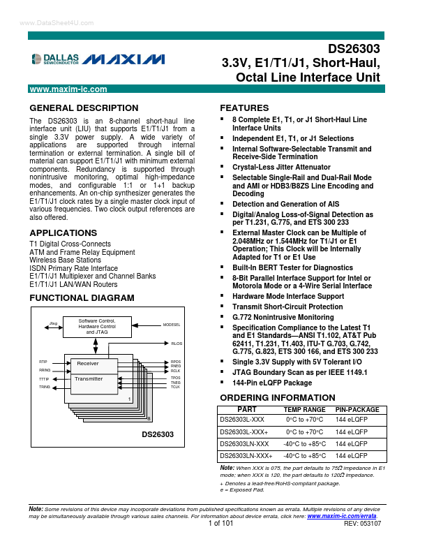
FUNCTIONAL DIAGRAM
Jtag
Software Control, Hardware Control and JTAG
MODESEL
RLOS
RTIP RRING TTTIP TRING
Receiver Transmitter
RPOS RNEG RCLK TPOS TNEG TCLK
ORDERING...