XP1001
XP1001 is GaAs MMIC Power Amplifier manufactured by Mimix Broadband.
Features
High Linearity Wideband Amplifier On-Chip Temperature pensated Output Power Detector Balanced Design Provides Good Input/Output Match 11.0 d B Small Signal Gain +31.0 d Bm Third Order Intercept (OIP3) 100% On-Wafer RF, DC and Output Power Testing 100% Visual Inspection to MIL-STD-883 Method 2010
General Description
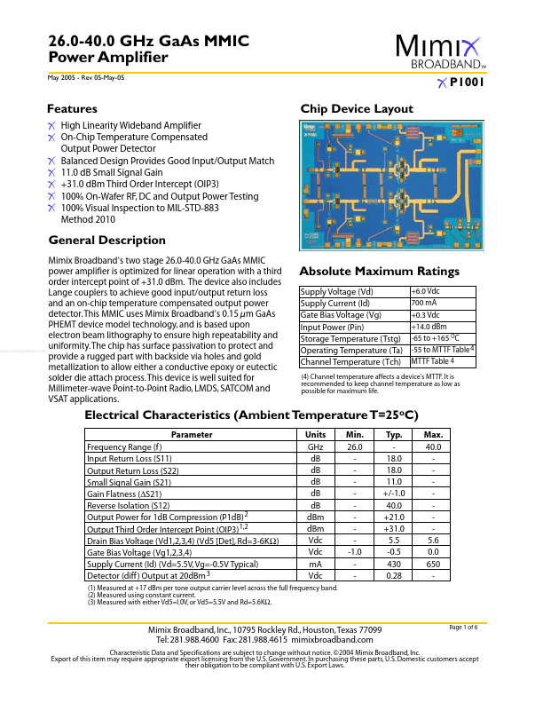
Mimix Broadband’s two stage 26.0-40.0 GHz Ga As MMIC power amplifier is optimized for linear operation with a third order intercept point of +31.0 d Bm. The device also includes Lange couplers to achieve good input/output return loss and an on-chip temperature pensated output power detector. This MMIC uses Mimix Broadband’s 0.15 µm Ga As PHEMT device model technology, and is based upon electron beam lithography to ensure high repeatability and uniformity. The chip has surface passivation to protect and .. provide a rugged part with backside via holes and gold metallization to allow either a conductive epoxy or eutectic solder die attach process. This device is well suited for Millimeter-wave Point-to-Point Radio, LMDS, SAT and VSAT applications.
Absolute Maximum Ratings
Supply Voltage (Vd) Supply Current (Id) Gate Bias Voltage (Vg) Input Power (Pin) Storage Temperature (Tstg) Operating Temperature (Ta) Channel Temperature (Tch)
+6.0 Vdc 700 m A +0.3 Vdc +14.0 d Bm -65 to +165 OC -55 to MTTF Table 4 MTTF Table 4
(4) Channel temperature affects a device's MTTF. It is remended to keep channel temperature as low as possible for maximum life.
Electrical Characteristics (Ambient Temperature T=25o C)
Parameter Frequency Range (f ) Input Return Loss (S11) Output Return Loss (S22) Small Signal Gain (S21) Gain Flatness (∆S21) Reverse Isolation (S12) Output Power for 1d B pression (P1d B) 2 Output Third Order Intercept Point (OIP3) 1,2 Drain Bias Voltage (Vd1,2,3,4) (Vd5 [Det], Rd=3-6K Ω ) Gate Bias Voltage (Vg1,2,3,4) Supply Current (Id) (Vd=5.5V, Vg=-0.5V Typical) Detector (diff ) Output at 20d Bm 3 Units GHz d B d B d B d B d B d Bm d Bm Vdc Vdc m A Vdc Min. 26.0 -1.0...