DESCRIPTION
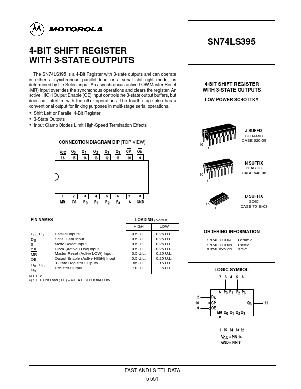
A LOW signal on the S input enables the serial inputs for shift-right operations, as indicated in the Truth Table. State changes are initiated by HIGH-to-LOW transitions on the Clock Pulse (CP) input. Signals on the Pn, Ds and S inputs can change when the Clock is in either state, provided that the recommended set-up and hold times are observed. When the S input is LOW, a CP HIGH-LOW transition transfers data in Q0 to Q1, Q1 to Q2, and Q2 to Q3. A left-shift is accomplished by connecting the outputs back to the Pn inputs, but offset one place to the left, i.e., O3 to P2, O2 to P1 and O1 to P0, with P3 acting as the linking input from another package. When the OE input is HIGH, the output buffers are disabled and the Q0 – Q3 outputs are in a high impedance condition. The shifting, parallel loading or resetting operations can still be accomplished, however. MODE SELECT — TRUTH TABLE Inputs @ tn Operating Mode Asynchronous Reset Shift, SET First Stage Shift, RESET First Stage... Motorola