Motorola 74LS74A
DUAL D-TYPE POSITIVE EDGE-TRIGGERED FLIP-FLOP
| Part No. | 74LS74A |
|---|---|
| Datasheet | 74LS74A Download |
| Manufacturer |  Motorola |
| Description | DUAL D-TYPE POSITIVE EDGE-TRIGGERED FLIP-FLOP |
| Buy | Stock & Price |
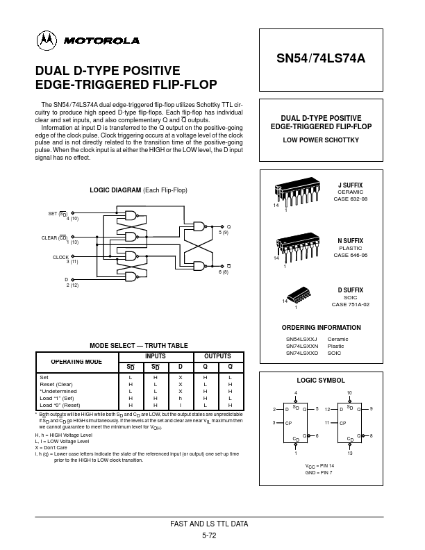
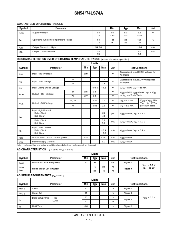
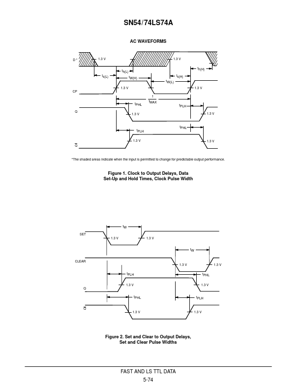
DUAL D-TYPE POSITIVE EDGE-TRIGGERED FLIP-FLOP The SN54 / 74LS74A dual edge-triggered flip-flop utilizes Schottky TTL circuitry to produce high speed D-type flip-flops. Each flip-flop has individual clear and set inputs, and also complementary Q and Q outputs. Information at input D is transferred to the Q output on the positive-going edge of the clock pulse. Clock triggering occurs at a voltage level of the clock pulse and is not directly related to the transition time of the positive-going pulse. When the clock input is at either the HIGH or the LOW level, the D input signal has no effect. LOGIC DIAGRAM (Each Flip-Flop) SET (SD)4 (10) CLEAR (CD) 1 (13) CLOCK 3 (11) D 2 (12) Q 5 (9) Q 6 (8) MODE SELECT — TRUTH TABLE OPERATING MODE INPUTS SD SD D OUTPUTS Q Q Set Reset (Clear) *Undetermined Load “1” (Set) Load “0” (Reset) L H X H L H L X L H L L X H H H H h H L H H l L H * Both outputs will be HIGH while both SD and CD are LOW, but the output states are unpredictable if SD and CD go HIGH simultaneously.