MRF21180R6
MRF21180R6 is RF Power Field Effect Transistor manufactured by Motorola Semiconductor.
MOTOROLA
SEMICONDUCTOR TECHNICAL DATA
Freescale Semiconductor, Inc.
Order this document by MRF21180/D
The RF Sub
- Micron MOSFET Line
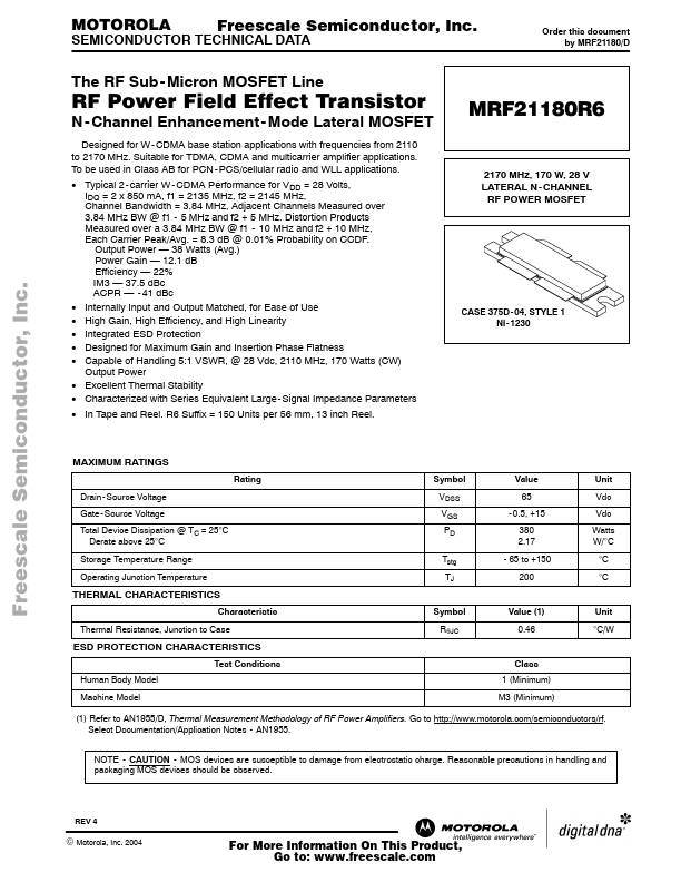
RF Power Field Effect Transistor
Designed for W- CDMA base station applications with frequencies from 2110 to 2170 MHz. Suitable for TDMA, CDMA and multicarrier amplifier applications. To be used in Class AB for PCN
- PCS/cellular radio and WLL applications.
- Typical 2
- carrier W
- CDMA Performance for VDD = 28 Volts, IDQ = 2 x 850 mA, f1 = 2135 MHz, f2 = 2145 MHz, Channel Bandwidth = 3.84 MHz, Adjacent Channels Measured over 3.84 MHz BW @ f1
- 5 MHz and f2 + 5 MHz. Distortion Products Measured over a 3.84 MHz BW @ f1
- 10 MHz and f2 + 10 MHz, Each...