MTD1N50E
MTD1N50E is TMOS POWER FET manufactured by Motorola Semiconductor.
MOTOROLA
SEMICONDUCTOR TECHNICAL DATA
Order this document by MTD1N50E/D
Designer's
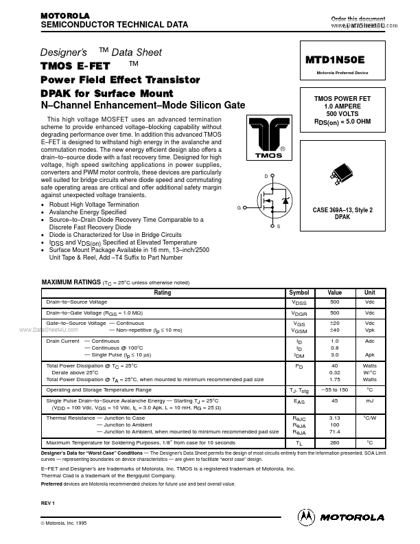
TMOS E-FET .™ Power Field Effect Transistor DPAK for Surface Mount N- Channel Enhancement- Mode Silicon Gate
This high voltage MOSFET uses an advanced termination scheme to provide enhanced voltage- blocking capability without degrading performance over time. In addition this advanced TMOS E- FET is designed to withstand high energy in the avalanche and mutation modes. The new energy efficient design also offers a drain- to- source diode with a fast recovery time. Designed for high voltage, high speed switching applications in power supplies, converters and PWM motor controls, these devices are particularly...