Datasheet4U Logo Datasheet4U.com

UPD16650 - 120-/128-OUTPUT TFT-LCD GATE DRIVER

General Description

Pin symbol X1 to X128 Pin name Driver output Description of function Output scan signals to drive the TFT-LCD gate electrodes.

The output changes when the shift clock φX rises.

The amplitude of the driver output is VDD - VEE1.

Key Features

  • Output with high dielectric strength (on/off range: VDD - VEE1 = 40 VMAX. ).
  • Built-in shift direction change-over function.
  • Shiftable negative supply voltage (VEE1) level (shift range: |VEE1 - VEE2| = 10 V).
  • Two acceptable CMOS input levels (3.3 and 5 V).
  • Output enable function.
  • MC-selectable output count (MC = high: 120-output mode) (MC = low : 128-output mode).
  • Slim TCP.

📥 Download Datasheet

Full PDF Text Transcription (Reference)

The following content is an automatically extracted verbatim text from the original manufacturer datasheet and is provided for reference purposes only.

View original datasheet text
DATA SHEET MOS INTEGRATED CIRCUIT µPD16650 120-/128-OUTPUT TFT-LCD GATE DRIVER 
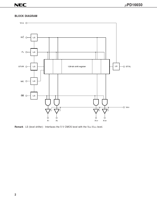
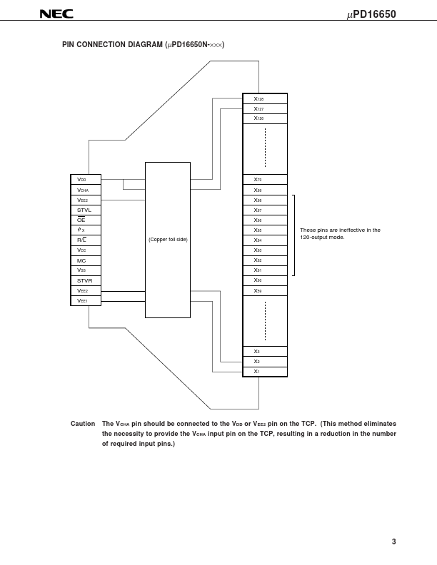
The µPD16650 is a TFT-LCD gate driver. Provided with a level shift circuit at the logic input, this chip can output a high gate scan voltage for a CMOS-level input. The µPD16650 has an output change-over function for switching from the 120-output mode to the 128-output mode, and vice versa, thereby supporting the VGA, SVGA, and XGA panels. Its output enable function (OE) enables installing the driver on either side. FEATURES • Output with high dielectric strength (on/off range: VDD - VEE1 = 40 VMAX.) • Built-in shift direction change-over function • Shiftable negative supply voltage (VEE1) level (shift range: |VEE1 - VEE2| = 10 V) • Two acceptable CMOS input levels (3.