BUK856-800A
BUK856-800A is Insulated Gate Bipolar Transistor IGBT manufactured by NXP Semiconductors.
DESCRIPTION
Fast-switching N-channel insulated gate bipolar power transistor in a plastic envelope. The device is intended for use in motor control, DC/DC and AC/DC converters, and in general purpose high frequency switching applications.
QUICK REFERENCE DATA
SYMBOL VCE IC Ptot VCEsat Eoff PARAMETER Collector-emitter voltage Collector current (DC) Total power dissipation Collector-emitter on-state voltage Turn-off energy Loss MAX. 800 24 125 3.5 1.0 UNIT V A W V m J
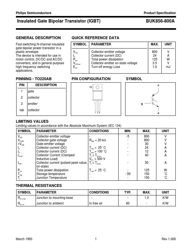
PINNING
- TO220AB
PIN 1 2 3 tab gate collector emitter collector DESCRIPTION
PIN CONFIGURATION tab
SYMBOL c g
1 23 e
LIMITING VALUES
Limiting values in accordance with the Absolute Maximum System (IEC 134) SYMBOL VCE VCGR ±VGE IC IC ICLM ICM Ptot Tstg Tj PARAMETER Collector-emitter voltage Collector-gate voltage Gate-emitter voltage Collector current (DC) Collector current (DC) Collector Current (Clamped Inductive Load) Collector current (pulsed peak value, on-state) Total power dissipation Storage temperature Junction Temperature CONDITIONS RGE = 20 kΩ Tmb = 25 ˚C Tmb = 100 ˚C Tj ≤ Tjmax. VCL ≤ 500 V Tj ≤ Tjmax. Tmb = 25 ˚C MIN. -5
- 55 MAX. 800 800 30 24 12 40 50 125 150 150 UNIT V V V A A A A W ˚C ˚C
THERMAL RESISTANCES
SYMBOL Rth j-mb Rth j-a PARAMETER Junction to mounting base Junction to ambient CONDITIONS In free air TYP. 60 MAX. 1.0 UNIT K/W K/W
March 1993
Rev 1.000
Philips Semiconductors
Product Specification
Insulated Gate Bipolar Transistor (IGBT)
STATIC CHARACTERISTICS
Tmb = 25 ˚C unless otherwise specified SYMBOL V(BR)CES VGE(TO) ICES ICES IECS IGES VCEsat PARAMETER Collector-emitter breakdown voltage Gate threshold voltage Zero gate voltage collector current Zero gate voltage collector current Reverse collector current Gate emitter leakage current Collector-emitter saturation voltage CONDITIONS VGE = 0 V; IC = 0.25 m A VCE = VGE; IC = 1 m A VCE = 800 V; VGE = 0 V; Tj = 25 ˚C VCE = 800 V; VGE = 0 V; Tj =125 ˚C VCE = -5 V; VGE = 0 V VGE = ±30 V; VCE = 0 V VGE = 15...