MMRF1312GS
Features
- Internally input and output matched for broadband operation and ease of use
- Device can be used in a single--ended, push--pull or quadrature configuration
- Qualified up to a maximum of 52 VDD operation
- High ruggedness, handles > 20:1 VSWR
- Integrated ESD protection with greater negative voltage range for improved
Class C operation and gate voltage pulsing
- Characterized with series equivalent large--signal impedance parameters
Typical Applications
- Air traffic control systems (ATC), including ground--based secondary radars such as IFF interrogators or transponders
- Distance measuring equipment (DME)
- Tactical air navigation (TACAN)
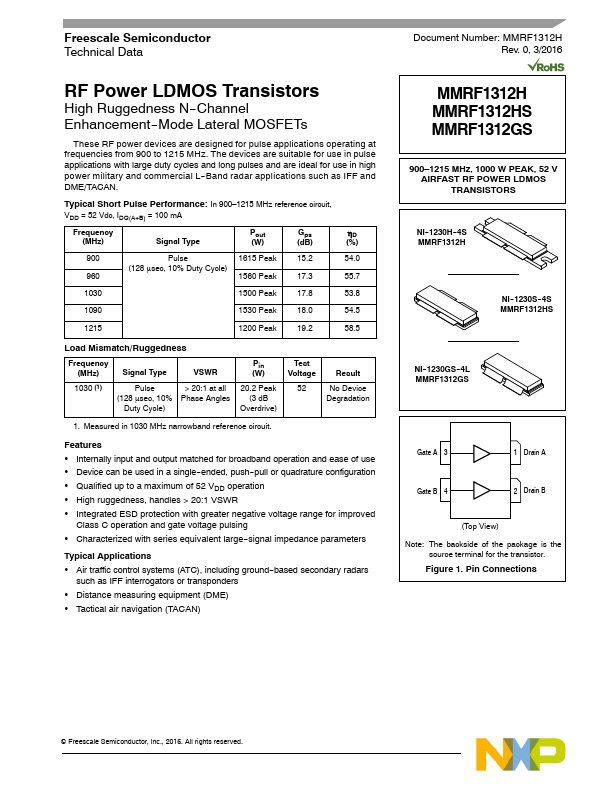
MMRF1312H MMRF1312HS MMRF1312GS
900- 1215 MHz, 1000 W PEAK, 52 V AIRFAST RF POWER LDMOS TRANSISTORS
NI--1230H--4S MMRF1312H
NI--1230S--4S MMRF1312HS
NI--1230GS--4L MMRF1312GS
Gate A 3
1 Drain A
Gate B 4
2 Drain B
(Top View)
Note: The backside of the package is the source terminal for the transistor.
Figure 1. Pin Connections
...