FDMC7200
Description
This device includes two specialized N- Channel MOSFETs in a dual Power 33 (3 mm x 3 mm MLP) package. The switch node has been internally connected to enable easy placement and routing of synchronous buck converters. The control MOSFET (Q1) and synchronous MOSFET (Q2) have been designed to provide optimal power efficiency.
Features
- Q1: N- Channel
- Max RDS(on) = 23.5 m W at VGS = 10 V, ID = 6 A
- Max RDS(on) = 38 m W at VGS = 4.5 V, ID = 5 A
- Q2: N- Channel
- Max RDS(on) = 12 m W at VGS = 10 V, ID = 8 A
- Max RDS(on) = 18 m W at VGS = 4.5 V, ID = 7 A
- This Device is Pb- Free, Halide Free and is Ro HS pliant
Applications
- Mobile puting
- Mobile Internet Devices
- General Purpose Point of Load
DATA SHEET .onsemi.
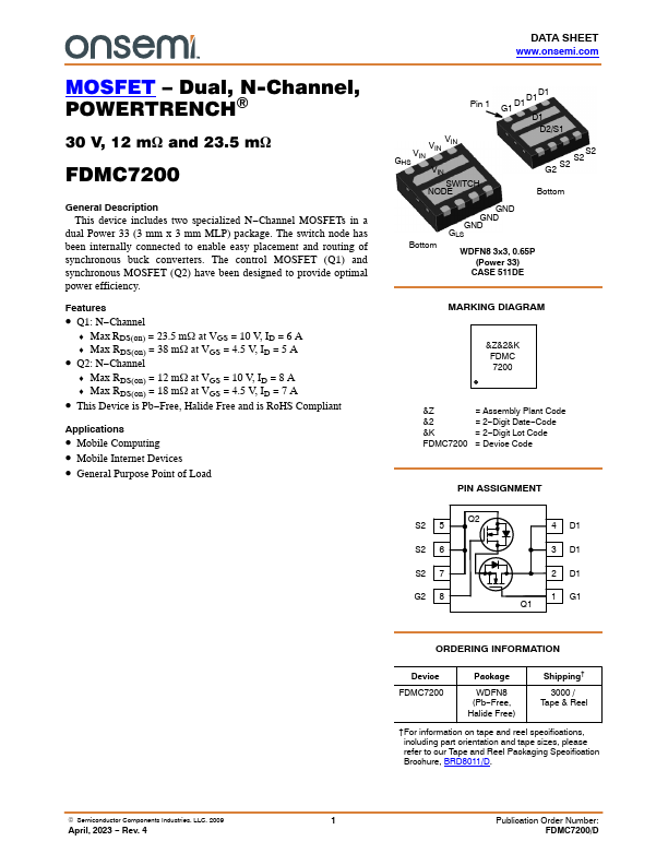
Pin 1
GHS VIN VIN VIN VIN SWITCH NODE
G1 D1 D1D1 D1 D2/S1
S2 S2 G2 S2
Bottom
Bottom
GND GND GND GLS
WDFN8 3x3, 0.65P (Power 33)
CASE 511DE
MARKING DIAGRAM
&Z&2&K FDMC 7200
&Z
= Assembly Plant Code
&2
= 2- Digit Date- Code
&K
= 2- Digit Lot Code
FDMC7200 =...