pc2402a Overview
Key Specifications
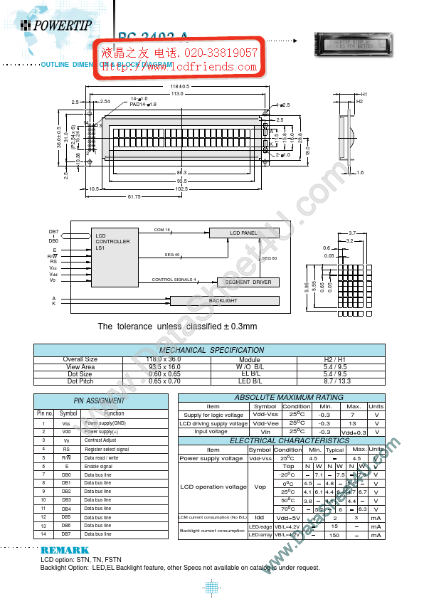
Key Features
- other Specs not available on catalog is under request
- w w w .D a S a t e e h 5.1 U 4 t m o .c
| Part | pc2402a |
|---|---|
| Description | LCD_Module |
| Manufacturer | POWERTIP |
| Size | 124.11 KB |
| Seller | Inventory | Price Breaks | Buy |
|---|---|---|---|
| No distributor offers were returned for this part. | |||
| Part Number | Manufacturer | Description |
|---|---|---|
| PC2402A-O | P-tec Corporation | Character Display |