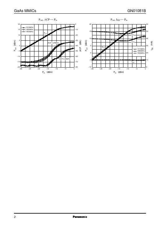
Datasheet4U Logo Datasheet4U.com

GN01081B Datasheet GaAs MMIC

Manufacturer: Panasonic

Overview

GaAs MMICs GN01081B GaAs IC (with built-in ferroelectric) 
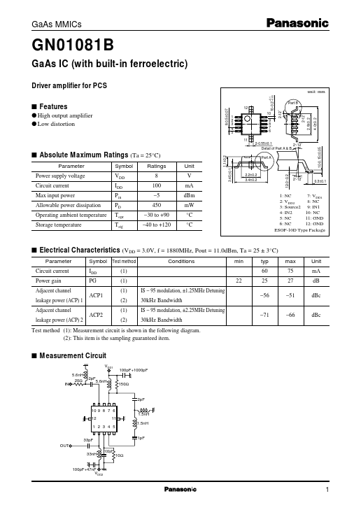
Driver amplifier for PCS unit: mm 10-0.2–0.05 +0.1 8-0.5±0.07 1 2 3 4 5 11 2-12˚ 2.8±0.2 12-0~0.2 2~12˚ 9 8 7 6 1.1±0.2 s Absolute Maximum Ratings (Ta = 25°C) Parameter Power supply voltage Circuit current Max input power Allowable power dissipation Operating ambient temperature Storage temperature Symbol VDD IDD Pin PD Topr Tstg Ratings 8 100 −5 450 −30 to +90 −40 to +120 Unit V mA dBm mW °C °C Part A 3.45±0.1 2.2±0.2 3.4±0.2 0.3±0.1 1: NC 7: VDD1 2: VDD2 8: NC 3: Source2 9: IN1 4: IN2 10: NC 5: NC 11: GND 6: NC 12: GND ESOF-10D Type Package s Electrical Characteristics (VDD = 3.0V, f = 1880MHz, Pout = 11.0dBm, Ta = 25 ± 3°C) Parameter Circuit current Power gain Adjacent channel leakage power (ACP) 1 Adjacent channel leakage power (ACP) 2 Symbol Test method IDD PG ACP1 (1) (1) (1) (2) (1) (2) IS − 95 modulation, ±1.25MHz Detuning 30kHz Bandwidth IS − 95 modulation, ±2.25MHz Detuning 30kHz Bandwidth 22 Conditions min typ 60 25 −56 −71 max 75 27 −51 −66 Unit mA dB dBc ACP2 dBc Test method (1): Measurement circuit is shown in the following diagram.

(2): This item is the sampling guaranteed item.

s Measurement Circuit VDD1 5.6nH 20Ω 2pF 5.6nH 100pF+1000pF 150Ω IN 2pF 10 9 8 7 6 12 11 1.5nH 1.5nH 1 2 3 4 5 33pF OUT 33nH 100pF 10Ω 1pF 100pF+47nF VDD2 10-0.15±0.05 2-0.55±0.1 2~12˚ Detail of Part A & B 4.0±0.

Key Features

  • Part B 12 1 GaAs MMICs Pout, ACP  Pin 20 15 10 1910MHz 1880MHz 1850MHz 0.
  • 10 Pout.
  • 20 10 15 20 GN01081B Pout, IDD  Pin 60 50 IDD 40 ACP (dBc) Pout (dBm) Pout (dBm) ACP 1.25MHz 0.
  • 5.
  • 10 ACP 2.25MHz.
  • 15.
  • 20.
  • 30.
  • 70.
  • 80.
  • 25.
  • 20.
  • 15.
  • 10.
  • 5 0.
  • 40.
  • 50.
  • 60 5 Pout 30 1910MHz 1880MHz 1850MHz 20 0.
  • 5 IDD1.
  • 10.
  • 30 10 0.
  • 25.