Datasheet Summary
Variable Capacitance Diodes
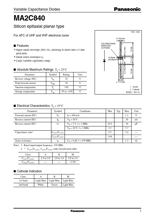
Silicon epitaxial planar type
Unit : mm
For AFC of UHF and VHF electronic tuner
φ 0.45 max.
Parameter Reverse voltage (DC) Peak forward current Junction temperature Storage temperature
Symbol VR VRM Tj Tstg
Rating 32 34 150
- 55 to +150
Unit
V V °C °C
φ 1.75 max.
1 : Anode 2 : Cathode JEDEC : DO-34
I Electrical Characteristics Ta = 25°C
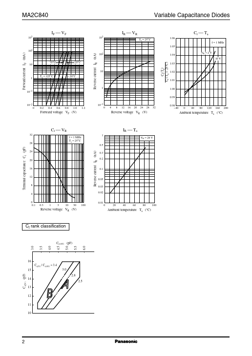
Parameter Forward current (DC) Reverse current (DC) Reverse current (DC) Capacitance ratio- Symbol VF IR Ct Ct(2V)/C t(10V) Ct(6V)/C t(10V) Series resistance rD CD = 9 pF, f = 470 MHz IF = 100 mA VR = 30 V VR = 2 V, f = 1 MHz VR = 10 V, f = 1 MHz 10.5 3.3 2.5 1.64 1.2 Conditions Min Typ Max 1.1 10 16 5.7 3.4 ...