RQG1004UPAQL
RQG1004UPAQL is NPN Silicon Germanium Transistor High Frequency Low Noise Amplifier manufactured by Renesas.
Features
- Ideal for LNA applications. e.g. Tuner, Wireless LAN, Cordless phone and etc.
- High gain and low noise. MSG = 25 d B typ. , NF = 0.65 d B typ. at VCE = 2 V, IC = 5 m A, f = 0.9 GHz MSG = 22 d B typ. , NF = 0.75 d B typ. at VCE = 2 V, IC = 5 m A, f = 1.8 GHz MSG = 21 d B typ. , NF = 0.85 d B typ. at VCE = 2 V, IC = 5 m A, f = 2.4 GHz MSG = 15 d B typ. , NF = 1.3 d B typ. at VCE = 2 V, IC = 10 m A, f = 5.8 GHz
- High transition frequency f T = 41 GHz typ.
- Small and low height package MFPAK-4 (1.4 x 0.8 x 0.55(max) mm)
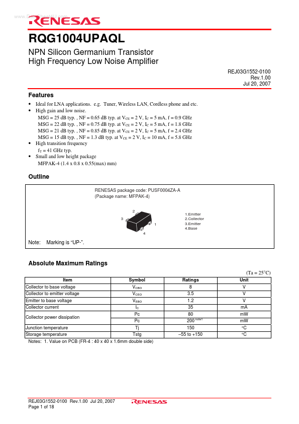
Outline
RENESAS package code: PUSF0004ZA-A (Package name: MFPAK-4)
2 3 1 4
1.Emitter 2.Collector 3.Emitter 4.Base
Note:
Marking is “UP-”.
Absolute Maximum Ratings
(Ta = 25°C)
Item Collector to base voltage Collector to emitter voltage Emitter to base voltage Collector current Collector power dissipation Junction temperature Storage temperature Symbol VCBO VCEO VEBO IC Pc Pc Tj Tstg Ratings 8 3.5 1.2 35 80 200 note1 150
- 55 to +150 Unit V V V m A m W m W °C °C
Notes: 1. Value on PCB (FR-4 : 40 x 40 x 1.6mm double side)
REJ03G1552-0100 Rev.1.00 Jul 20, 2007 Page 1 of 18
Electrical Characteristics
(Ta = 25°C)
Item DC current transfer ratio Reverse Transfer Capacitance Transition Frequency 0.9 GHz 1.5 GHz Forward Transfer Coefficient 2.4 GHz 5.8 GHz 0.9 GHz Maximum Stable Gain
Note1
Symbol h FE Cre f T |S21|2
Min. 150
Typ 180 0.07 41 18.5 17.5 16.5 10.5 23 21 19 16 12.5 18 11.5 0.7 1.3
Max. 230
Unit p F GHz
Test Conditions VCE = 2 V, IC = 3 m A VCB = 2 V, IE = 0, f = 1 MHz VCE = 2 V, IC = f T peak, f = 1 GHz VCE = 2 V, IC = 3 m A VCE = 2 V, IC = 10 m A VCE = 2 V, IC = 3 m A VCE = 2 V, IC = 10 m A d B
1.5 GHz 2.4 GHz 5.8 GHz 5.8 GHz 1.5 GHz 5.8 GHz 1.5 GHz 5.8 GHz
MSG d B
Maximum Available Gain
Note2
MAG PG NF d B d B d B
VCE = 2 V, IC = 10 m A VCE = 2 V, IC = 3 m A VCE = 2 V, IC = 10 m A VCE = 2 V, IC = 3 m A VCE = 2 V, IC = 10 m A
Power Gain Noise figure
Notes: 1. MSG = |S21| /...