SST45VF020
SST45VF020 is (SST45VFxxx) 512 Kbit / 1 Mbit / 2 Mbit Serial Flash manufactured by SST.
- Part of the SST45VF010 comparator family.
- Part of the SST45VF010 comparator family.
FEATURES
:
- Single 2.7-3.6V Read and Write Operations
- Serial Interface Architecture
- SPI patible: Mode 0 and Mode 3
- Byte Serial Read with Single mand
- Superior Reliability
- Endurance: 100,000 Cycles (typical)
- Greater than 100 years Data Retention
- Low Power Consumption:
- Active Current: 20 m A (typical)
- Standby Current: 10 µA (typical)
- Sector or Chip-Erase Capability
- Uniform 4 KByte sectors
- Fast Erase and Byte-Program:
- Chip-Erase Time: 70 ms (typical)
- Sector-Erase Time: 18 ms (typical)
- Byte-Program Time: 14 µs (typical)
- Automatic Write Timing
- Internal VPP Generation
- End-of-Write Detection
- Software Status
- 10 MHz Max Clock Frequency
- Hardware Reset Pin (RESET#)
- Resets the device to Standby Mode
- CMOS I/O patibility
- Hardware Data Protection
- Protects and unprotects the device from Write operation
- Packages Available
- 8-Pin SOIC (4.9mm x 6mm)
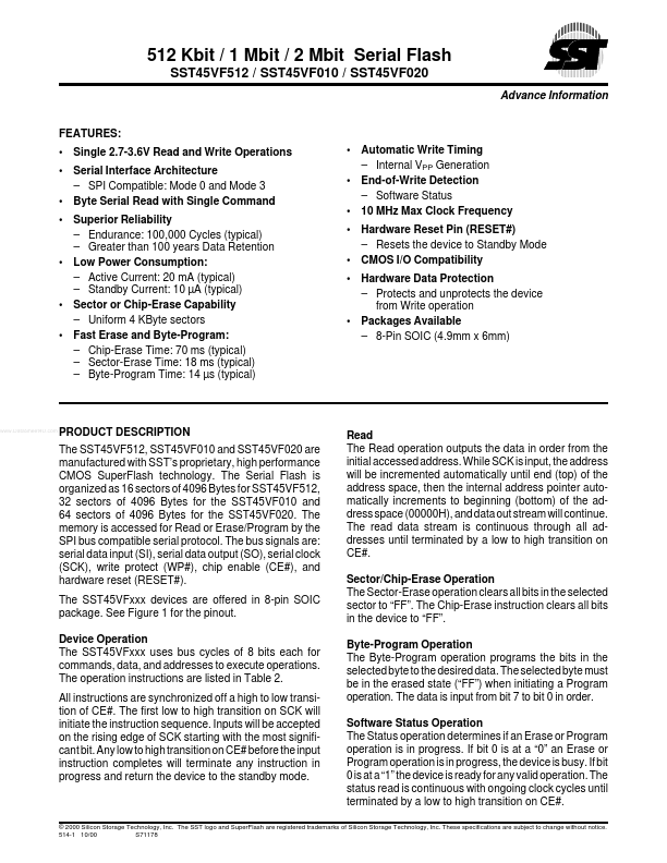
1 2 3 4 5 6 7
..
PRODUCT DESCRIPTION
The SST45VF512, SST45VF010 and SST45VF020 are manufactured with SST’s proprietary, high performance CMOS Super Flash technology. The Serial Flash is organized as 16 sectors of 4096 Bytes for SST45VF512, 32 sectors of 4096 Bytes for the SST45VF010 and 64 sectors of 4096 Bytes for the SST45VF020. The memory is accessed for Read or Erase/Program by the SPI bus patible serial protocol. The bus signals are: serial data input (SI), serial data output (SO), serial clock (SCK), write protect (WP#), chip enable (CE#), and hardware reset (RESET#). The SST45VFxxx devices are offered in 8-pin SOIC package. See Figure 1 for the pinout. Device Operation The SST45VFxxx uses bus cycles of 8 bits each for mands, data, and addresses to execute operations. The operation instructions are listed in Table 2. All instructions are synchronized off a high to low transition of CE#. The first low to high transition on SCK will initiate the instruction sequence. Inputs will be accepted on the rising edge of SCK starting with the most significant bit. Any low to high transition...