STGB7NB60FD
STGB7NB60FD is N-CHANNEL IGBT manufactured by STMicroelectronics.
- Part of the STGP7NB60FD comparator family.
- Part of the STGP7NB60FD comparator family.
STGP7NB60FD
- STGB7NB60FD
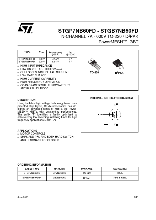
N-CHANNEL 7A
- 600V TO-220 / D2PAK Power MESH™ IGBT
TYPE STGP7NB60FD STGB7NB60FD s s s s s s s
VCES 600 V 600 V
VCE(sat) (Max) @25°C < 2.4 V < 2.4 V
IC @100°C 7A 7A
3 1 2
HIGH INPUT IMPEDANCE LOW ON-VOLTAGE DROP (Vcesat) OFF LOSSES INCLUDE TAIL CURRENT LOW GATE CHARGE HIGH CURRENT CAPABILITY HIGH FREQUENCY OPERATION CO-PACKAGED WITH TURBOSWITCH™ ANTIPARALLEL DIODE
3 1
TO-220
D2PAK
DESCRIPTION Using the latest high voltage technology based on a patented strip layout, STMicroelectronics has designed an advanced family of IGBTs, the Power MESH™ IGBTs, with outstanding perfomances. The suffix "F" identifies a family optimized to achieve very low switching switching times for high frequency applications (<40KHZ)
INTERNAL SCHEMATIC DIAGRAM
APPLICATIONS MOTOR CONTROLS s SMPS AND PFC AND BOTH HARD SWITCH AND RESONANT TOPOLOGIES s
ORDERING INFORMATION
SALES TYPE STGP7NB60FD STGB7NB60FDT4 MARKING GP7NB60FD GB7NB60FD PACKAGE TO-220 D2PAK PACKAGING TUBE TAPE & REEL
June 2003
1/11
STGP7NB60FD
-...