APPLICATIONS
ELECTRONIC BALLAST FOR FLUORESCENT LIGHTING s SWITCH MODE POWER SUPPLIES s DESCRIPTION
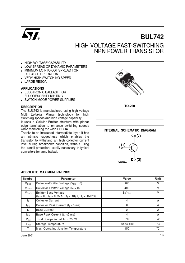
Thanks to an increased intermediate layer, it has an intrinsic ruggedness which enables the transistor to withstand an high collector current level during breakdown condition, without using the transil protection usually necessary in typical converters for lamp ballast. TO-220 INTERNAL SCHEMATIC DIAGRAM ABSOLUTE MAXIMUM RATINGS
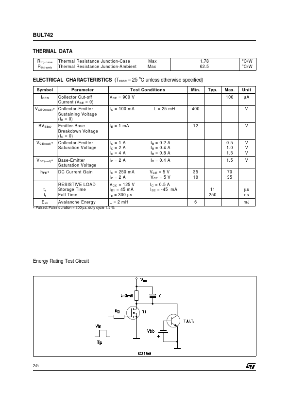
Symbol V CES V CEO V EBO IC I CM IB I BM P tot T stg Tj June 2001 Parameter Collector-Emitter Voltage (V BE = 0) Collector-Emitter Voltage (I B = 0) Emitter-Base Voltage (I C = 0, I B = 0.75 A, t p < 10 µ s, T j < 150 o C) Collector Current Collector Peak Current (t p <5 ms) Base Current Base Peak Current (t p <5 ms) Total Dissipation at Tc = 25 C Storage Temperature Max. Operating Junction Temperature o Value 900 400 BV EBO 4 8 2 4 70 -65 to 150 150 Unit V V V A A A A W o o C C 1/5 BUL742 THERMAL DATA R thj-case R thj-amb Thermal Resistance Junction-Case Thermal... STMicroelectronics