FERD40U45C
FERD40U45C is Field effect rectifier manufactured by STMicroelectronics.
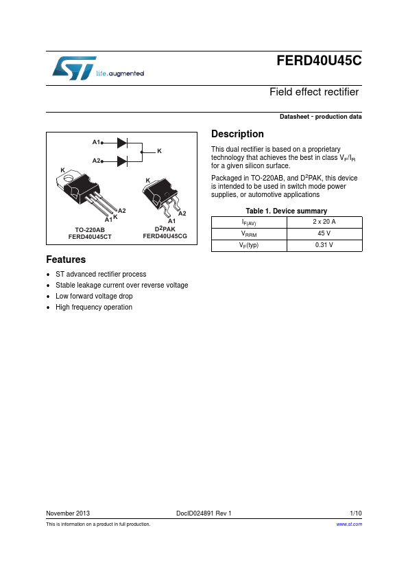
Description
This dual rectifier is based on a proprietary technology that achieves the best in class VF/IR for a given silicon surface. Packaged in TO-220AB, and D2PAK, this device is intended to be used in switch mode power supplies, or automotive applications
A2 A1 D2PAK FERD40U45CG
A1 K TO-220AB FERD40U45CT
A2
Table 1. Device summary
IF(AV) VRRM VF(typ) 2 x 20 A 45 V 0.31 V
Features
- ST advanced rectifier process
- Stable leakage current over reverse voltage
- Low forward voltage drop
- High frequency operation
November 2013
This is information on a product in full production.
Doc ID024891 Rev 1
1/10
.st.
Characteristics
Characteristics
Table 2. Absolute ratings (limiting values, per diode at 25° C, unless otherwise stated)
Symbol VRRM IF(RMS) IF(AV) IFSM Tstg Tj
1. d Ptot --------------d Tj
Parameter Repetitive peak reverse voltage Forward rms current Average forward current, = 0.5 Surge non repetitive forward current Storage temperature range Maximum operating junction temperature (1)
TO-220AB, D2PAK D2PAK (DC forward current without reverse bias, t = 1 hour)
Value 45 40
Unit V A A A °C
Tc =150° C Tc =145° C
Per diode Per device
20 40 275 -65 to + 175 175 tp = 10 ms sinusoidal
°C 200
- condition to avoid thermal runaway for a diode on its own heatsink ------------------------Rth j
- a
Table 3. Thermal resistances
Symbol Rth (j-c) Rth(c) Junction to case Coupling Parameter Per diode Total Value 1.6 1.1 0.5 Unit °C/W °C/W
When the diodes 1 and 2 are used simultaneously:
Tj(diode 1) = P(diode1) x Rth(j-c)(Per diode) + P(diode2) x Rth(c).
Table 4. Static electrical characteristics (per diode)
Symbol IR(1) Parameter Reverse leakage current Test Conditions Tj = 25° C Tj = 125° C Tj = 25° C VF(2) Forward voltage drop Tj = 125° C Tj = 25° C Tj = 125° C
1. Pulse test: tp = 5 ms, < 2% 2. Pulse test: tp = 380 µs, <...