LNBK14
LNBK14 is LNB SUPPLY AND CONTROL VOLTAGE REGULATOR PARALLEL INTERFACE manufactured by STMicroelectronics.
®
LNBK10 SERIES LNBK20
LNB SUPPLY AND CONTROL VOLTAGE REGULATOR (PARALLEL INTERFACE) s s s s s s s s s s s s
REDUCED OUTPUT CURRENT VERSION OF LNBP1X AND LNBP20 SERIES PLETE INTERFACE FOR TWO LNBs REMOTE SUPPLY AND CONTROL LNB SELECTION AND STAND-BY FUNCTION BUILT-IN TONE OSCILLATOR FACTORY TRIMMED AT 22KHz FAST OSCILLATOR START-UP FACILITATES Di SEq C™ ENCODING TWO SUPPLY INPUTS FOR LOWEST DISSIPATION BYPASS FUNCTION FOR SLAVE OPERATION LNB SHORT CIRCUIT PROTECTION AND DIAGNOSTIC AUXILIARY MODULATION INPUT EXTENDS FLEXIBILITY CABLE LENGTH PENSATION INTERNAL OVER TEMPERATURE PROTECTION BACKWARD CURRENT PROTECTION
Multiwatt-15
Power So-20
Power SO-10
DESCRIPTION 
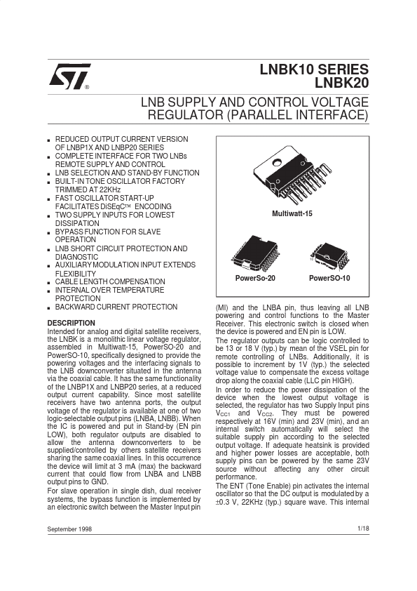
Intended for analog and digital satellite receivers, the LNBK is a monolithic linear voltage regulator, assembled in Multiwatt-15, Power SO-20 and Power SO-10, specifically designed to provide the powering voltages and the interfacing signals to the LNB downconverter situated in the antenna via the coaxial cable. It has the same functionality of the LNBP1X and LNBP20 series, at a reduced output current capability. Since most satellite receivers have two antenna ports, the output voltage of the regulator is available at one of two logic-selectable output pins (LNBA, LNBB). When the IC is powered and put in Stand-by (EN pin LOW), both regulator outputs are disabled to allow the antenna downconverters to be supplied/controlled by others satellite receivers sharing the same coaxial lines. In this occurrence the device will limit at 3 m A (max) the backward current that could flow from LNBA and LNBB output pins to GND. For slave operation in single dish, dual receiver systems, the bypass function is implemented by an electronic switch between the Master Input pin
September 1998
(MI) and the LNBA pin, thus leaving all LNB powering and control functions to the Master Receiver. This electronic switch is closed when the device is powered and EN pin is LOW. The regulator outputs can be logic...