STIL04-P5
STIL04-P5 is AC inrush current limiter manufactured by STMicroelectronics.
®
A.S.D.TM
Application Specific Discretes
AC inrush current limiter
.. HIGH s s
MAIN APPLICATIONS POWER DENSITY ADAPTER HIGH END TV POWER SUPPLY OPENED FRAME SMPS s
Features
Inrush current limitation circuit for off-line power supply Dual non-sensitive unidirectional switches in a single package Suitable when space and efficiency are critical Active after short AC line drop out with a boost converter High repetitive forward and reverse off-state voltage (700V) s s s s s
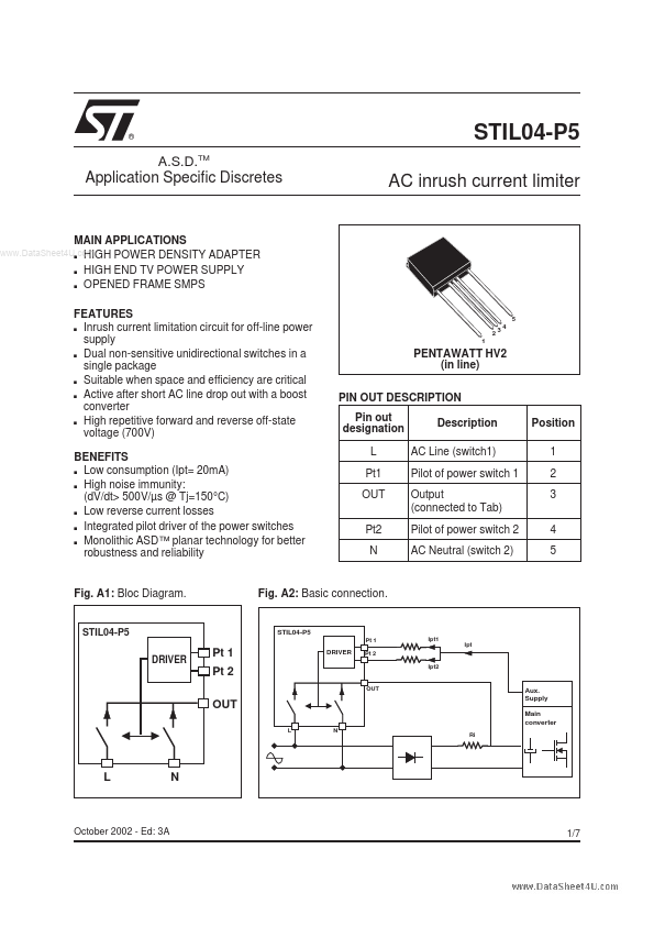
5 23 1 4
PENTAWATT HV2 (in line) PIN OUT DESCRIPTION Pin out designation L Pt1 OUT Pt2 N Description AC Line (switch1) Pilot of power switch 1 Output (connected to Tab) Pilot of power switch 2 AC Neutral (switch 2) Position 1 2 3 4 5
BENEFITS Low consumption (Ipt= 20m A) High noise immunity: (d V/dt> 500V/µs @ Tj=150°C) Low reverse current losses Integrated pilot driver of the power switches Monolithic ASD™ planar technology for better robustness and reliability s s s s s
Fig. A1: Bloc Diagram.
Fig. A2: Basic connection.
DRIVER
Pt 1
Ipt1
Ipt
Pt 1 Pt 2
DRIVER
Pt 2 Ipt2
L N Ri
Aux. Supply Main converter
October 2002
- Ed: 3A
1/7
Functional Description The STIL04 is connected in parallel with the bridge diode and the inrush power resistor Ri (fig. A2). During start up, the two unidirectional ASD™ power switches of the STIL04 are opened. The inrush current flows through the diodes of the bridge and the external inrush power resistor Ri. Since the main converter turns ON, the auxiliary power supply coupled with the main transformer, supplies the energy required to close the two power switches of the STIL04. At the normal state, the two bottom diodes of the bridge rectifier and the two unidirectional switches of the STIL04 rectify the AC line current. When the STIL04 is used with a PFC boost converter, the inrush current circuit remains active after a short AC line dropout (see fig. A5). In that configuration,...