BFP520 Overview
Key Specifications
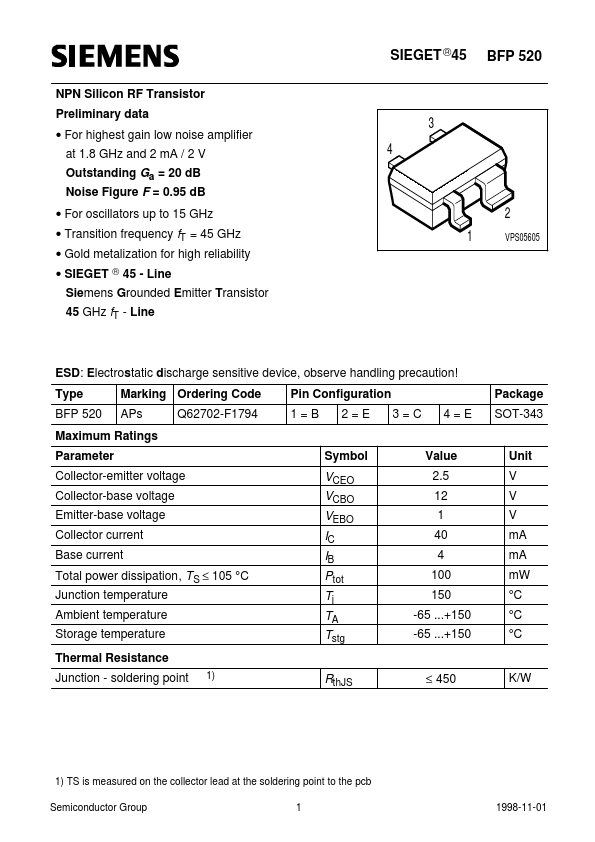
Package: SOT
Mount Type: Surface Mount
Pins: 4
Max Frequency: 6 GHz
Key Features
- For highest gain low noise amplifier at 1.8 GHz and 2 mA / 2 V Outstanding Ga = 20 dB Noise Figure F = 0.95 dB
- For oscillators up to 15 GHz