TA1319AF
TA1319AF is manufactured by Toshiba.
TA1319AP/AF
Toshiba Bipolar Linear IC
- Silicon Monolithic
TA1319AP/AF
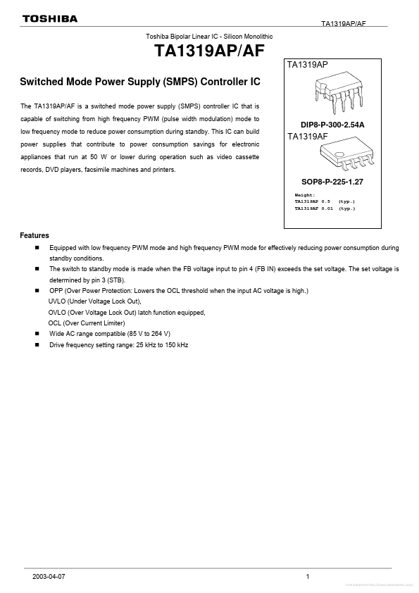
TA1319AP
Switched Mode Power Supply (SMPS) Controller IC
The TA1319AP/AF is a switched mode power supply (SMPS) controller IC that is capable of switching from high frequency PWM (pulse width modulation) mode to low frequency mode to reduce power consumption during standby. This IC can build power supplies that contribute to power consumption savings for electronic appliances that run at 50 W or lower during operation such as video cassette records, DVD players, facsimile machines and printers.
DIP8-P-300-2.54A
SOP8-P-225-1.27
Weight: TA1319AP 0.5‚‡ (typ.) TA1319AF 0.01‚‡ (typ.)
Features
Equipped with low...