Datasheet4U Logo Datasheet4U.com

TB6592FL - Dual-Bridge Driver IC

Description

Remarks GND AIN1 AIN2 APWM ASTBY AO1 AO2 PGND VM BO2 BO1 BSTBY BPWM BIN2 BIN1 VCC 21 Small-signal GND pin 18 Control signal input 1 (Channel A) GND for small-signal power supply (VCC) 17 Control signal input 2 (Channel A) 16 PWM control signal input pin (Channel A) Input PWM signal 15 Standby

Features

  • Power supply voltage for motor: VM ≤ 6 V (max).
  • Power supply voltage for control: VCC = 2.7 V to 6.0 V.
  • Output current: IOUT = 0.8 A (max) Weight: 0.05 g (typ. ).
  • Low ON resistor: 1.5 Ω (typ. ) (Upper side + Lower side combined @ VM = 5 V, VCC = 5 V).
  • Direct PWM control.
  • Standby system (Power save).
  • CW/CCW/short brake/stop function modes.
  • Built-in thermal shutdown circuit.
  • Small-size leadless package: QON24-P-0505-0.50.
  • This product h.

📥 Download Datasheet

Datasheet preview – TB6592FL

Datasheet Details

Part number TB6592FL
Manufacturer Toshiba
File Size 129.32 KB
Description Dual-Bridge Driver IC
Datasheet download datasheet TB6592FL Datasheet
Additional preview pages of the TB6592FL datasheet.
Other Datasheets by Toshiba

Full PDF Text Transcription

Click to expand full text
Toshiba Bi-CD Integrated Circuit Silicon Monolithic TB6592FL Dual-Bridge Driver IC for DC motor TB6592FL is a dual-bridge driver IC for DC motor with output transistor in LD MOS structure with low ON-resistor. Two input signals, IN1 and IN2, can chose one of four modes such as CW, CCW, short brake, and stop mode. Efficient driven at high temperature is possible by PWM drive system. TB6592FL Features · Power supply voltage for motor: VM ≤ 6 V (max) · Power supply voltage for control: VCC = 2.7 V to 6.0 V · Output current: IOUT = 0.8 A (max) 
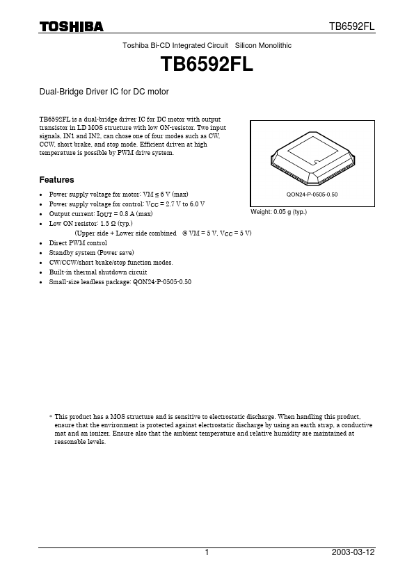
Weight: 0.05 g (typ.) · Low ON resistor: 1.5 Ω (typ.) (Upper side + Lower side combined @ VM = 5 V, VCC = 5 V) · Direct PWM control · Standby system (Power save) · CW/CCW/short brake/stop function modes.
Published: |