PH1214-12M
PH1214-12M is Radar Pulsed Power Transistor - 12 Watts/1.20-1.40 GHz/ 150 mS Pulse/ 10% Duty manufactured by Tyco Electronics.
Features
- -
- -
- -
- - NPN Silicon Microwave Power Transistor mon Base Configuration Broadband Class C Operation High Efficiency Interdigitated Geometry Diffused Emitter Ballasting Resistors Gold Metalization System Internal Input and Output Impedance Matching Hermetic Metal/Ceramic Package
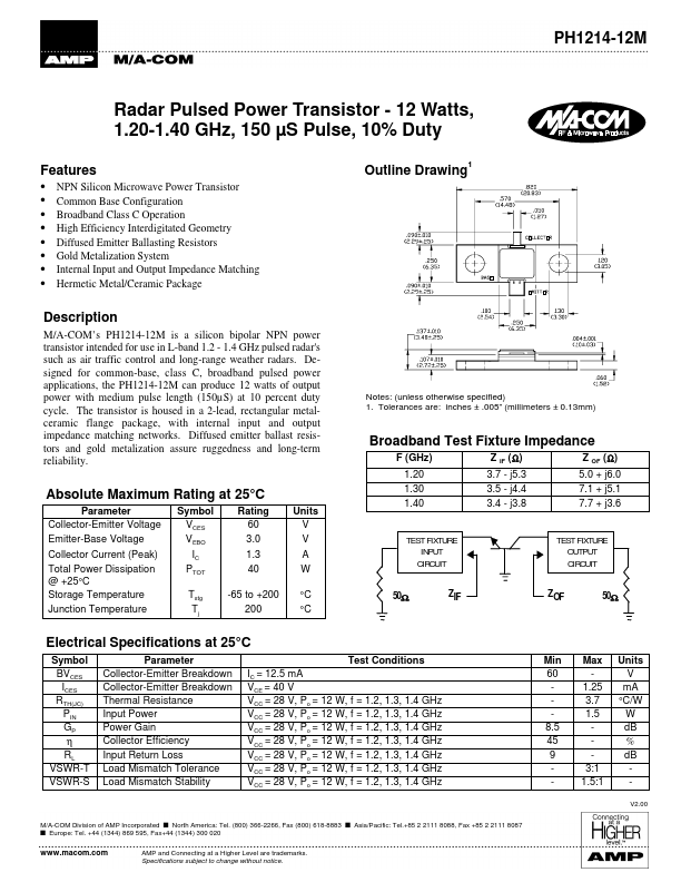
Outline Drawing
Description
M/A-’s PH1214-12M is a silicon bipolar NPN power transistor intended for use in L-band 1.2
- 1.4 GHz pulsed radar's such as air traffic control and long-range weather radars. Designed for mon-base, class C, broadband pulsed power applications, the PH1214-12M can produce 12 watts of output power with medium pulse length (150µS) at 10 percent duty cycle. The transistor is housed in a 2-lead, rectangular metalceramic flange package, with internal input and output impedance matching networks. Diffused emitter ballast resistors and gold metalization assure ruggedness and long-term reliability.
Notes: (unless otherwise specified) 1. Tolerances are: inches ± .005” (millimeters ± 0.13mm)
Broadband Test Fixture Impedance
F (GHz) 1.20 1.30 1.40 Z IF (Ω) 3.7
- j5.3 3.5
- j4.4 3.4
- j3.8 Z OF (Ω) 5.0 + j6.0 7.1 + j5.1 7.7 + j3.6
Absolute Maximum Rating at 25°C
Parameter Collector-Emitter Voltage Emitter-Base Voltage Collector Current (Peak) Total Power Dissipation @ +25°C Storage Temperature Junction Temperature Symbol VCES VEBO IC PTOT Tstg Tj Rating 60 3.0 1.3 40 -65 to +200 200 Units V V A W °C °C
TEST FIXTURE INPUT CIRCUIT
TEST FIXTURE OUTPUT CIRCUIT
50Ω
50Ω
Electrical Specifications at 25°C
Symbol BVCES ICES RTH(JC) PIN GP η RL VSWR-T VSWR-S Parameter Collector-Emitter Breakdown Collector-Emitter Breakdown Thermal Resistance Input Power Power Gain Collector Efficiency Input Return Loss Load Mismatch Tolerance Load Mismatch Stability Test Conditions IC = 12.5 m A VCE = 40 V VCC = 28 V, Po = 12 W, f = 1.2, 1.3, 1.4 GHz VCC = 28 V, Po = 12 W, f = 1.2, 1.3, 1.4 GHz VCC = 28 V, Po = 12 W, f = 1.2, 1.3, 1.4 GHz VCC = 28 V, Po = 12 W, f =...