PH1214-300M
PH1214-300M is Radar Pulsed Power Transistor/ 300 Watts/1.20-1.40 GHz/ 150 mS Pulse/ 10% Duty manufactured by Tyco Electronics.
Features
Q Q Q Q Q Q Q
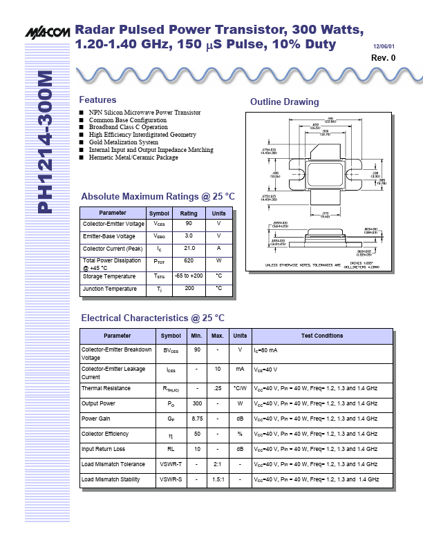
Outline Drawing
NPN Silicon Microwave Power Transistor mon Base Configuration Broadband Class C Operation High Efficiency Interdigitated Geometry Gold Metalization System Internal Input and Output Impedance Matching Hermetic Metal/Ceramic Package
Absolute Maximum Ratings @ 25 °C
Parameter Collector-Emitter Voltage Emitter-Base Voltage Collector Current (Peak) Total Power Dissipation @ +45 °C Storage Temperature Junction Temperature Symbol VCES VEBO IC PTOT TSTG Tj Rating 90 3.0 21.0 620 -65 to +200 200 Units V V A W °C °C
Electrical Characteristics @ 25 °C
Parameter Collector-Emitter Breakdown Voltage Collector-Emitter Leakage Current Thermal Resistance Output Power Power Gain Collector Efficiency Input Return Loss Load Mismatch Tolerance Load Mismatch Stability Symbol BVCES ICES RTH(JC) PO GP Min. 90 300 8.75 50 10 Max. 10 .25 2:1 1.5:1 Units V m A °C/W W d B % d B IC=80 m A VCE=40 V VCC=40 V, Pin = 40 W, Freq= 1.2, 1.3 and 1.4 GHz VCC=40 V, Pin = 40 W, Freq= 1.2, 1.3 and 1.4 GHz VCC=40 V, Pin = 40 W, Freq= 1.2, 1.3 and 1.4 GHz VCC=40 V, Pin = 40 W, Freq= 1.2, 1.3 and 1.4 GHz VCC=40 V, Pin = 40 W, Freq= 1.2, 1.3 and 1.4 GHz VCC=40 V, Pin = 40 W, Freq= 1.2, 1.3 and 1.4 GHz VCC=40 V, Pin = 40 W, Freq= 1.2, 1.3 and 1.4 GHz Test Conditions
η
RL VSWR-T VSWR-S
Radar Pulsed Power Transistor, 300 Watts, 1.20-1.40 GHz, 150µS Pulse, 10% Duty
12/06/01
Sample Test Data
(Broadband test fixture matched to 50 Ω.)
P1d B Overdrive Freq. (GHz) Pin (W) Pout (W) Gain (d B) ∆Gain (d B) Eff. (%) Ic (A) Droop (d B) RL (d B) Pout (W) 451 ∆ Po (d B) 0.46 Gain (d B) 9.52 Droop (d B) 0.38 Eff. (%) 59.8
Rev. 0
VSWR-S
1.5:1
2:1
2.5:1
9.48 0.82
Note: ∆Po(d B) is the difference between Pout at 1d B overdrive and Pout at Pin = 40W.
Power Output Curves
PH1214-3...