Texas Instruments 74AC11646
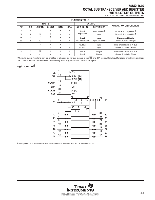
The 74AC11646 consists of bus transceiver circuits, D-type flip-flops, and control circuitry arranged for multiplexed transmission of data directly from the input bus or from the internal registers. The 74AC11646 is characterized for operation from − 40°C to 85°C.| Part No. | 74AC11646 |
|---|---|
| Datasheet | 74AC11646 Download |
| Manufacturer |  Texas Instruments |
| Description | OCTAL BUS TRANSCEIVER AND REGISTER |
| Buy | Stock & Price |
ăą
● Independent Registers for A and B Buses
● Multiplexed Real-Time and Stored Data
● Flow-Through Architecture Optimizes PCB Layout
● Center-Pin VCC and GND Configurations Minimize High-Speed Switching Noise
● EPIC (Enhanced-Performance Implanted CMOS) 1-µm Process
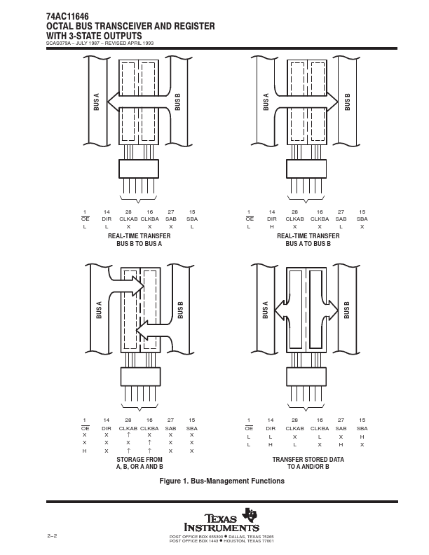
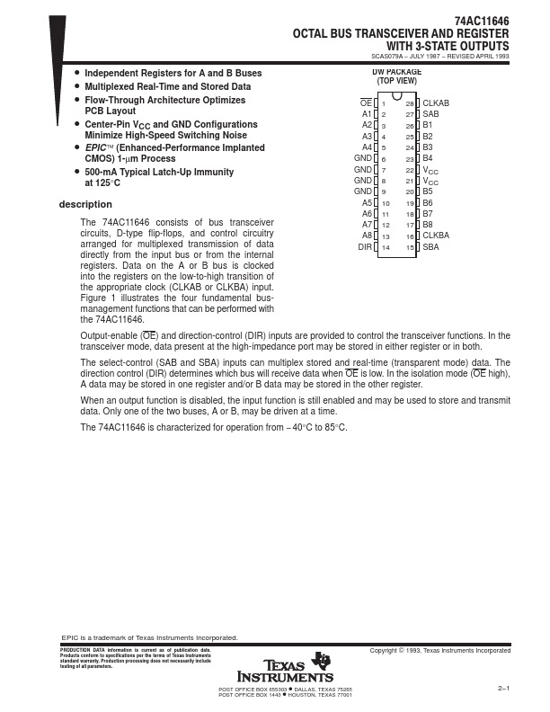
● 500-mA Typical Latch-Up Immunity at 125°C description Data on the A or B bus is clocked into the registers on the low-to-high transition of the appropriate clock (CLKAB or CLKBA) input. Figure 1 illustrates the four fundamental busmanagement functions that can be performed with the 74AC11646. 74AC11646 OCTAL BUS TRANSCEIVER AND REGISTER WITH 3ĆSTATE OUTPUTS SCAS079A − JULY 1987 − REVISED APRIL 1993 DW PACKAGE (TOP VIEW) OE A1 A2 A3 A4 GND GND GND GND A5 A6 A7 A8 DIR 1 2 3 4 5 6 7 8 9 10 11 12 13 14 28 CLKAB 27 SAB 26 B1 25 B2 24 B3 23 B4 22 VCC 21 VCC 20 B5 19 B6 18 B7 17 B8 16 CLKBA 15 SBA Output-enable (OE) and direction-control (DIR) inputs are provided to control the transceiver functions. In the transceiver mode, data present at the high-impedance port may be stored in either register or in both.